


|
|
ESP32-S3-WROOM-1U-N4 |
x 1 | |

|
1447Adafruit Industries LLC
|
x 1 | |

|
Touch Sensor Module |
x 1 | |
|
|
Buzzer |
x 1 | |
|
QBL8RGB60D0-2897QT Brightek (QTB)
|
x 1 | |
|
|
Micro USB Cable |
x 1 | |
|
|
220 Ohm Resistor |
x 1 | |
|
|
1K Ohm Resistor |
x 1 | |

|
BC547onsemi
|
x 1 |
ESP-32 Morse Code Trainer
Introduction
In this project, we will create a Morse Code Trainer using an ESP32 board, a momentary touch sensor, a serial-enabled 16x2 LCD, a buzzer for sound feedback, and an RGB LED for visual feedback. The user can input Morse code by pressing the touch sensor, and the decoded letters will be displayed on the LCD.
Components Needed
- ESP32 Development Board
- Momentary Touch Sensor (e.g., TTP223)
- 16x2 LCD with I2C Interface
- Buzzer (Piezo Buzzer)
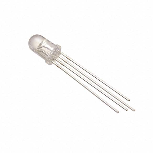
- Common Anode RGB LED
- Resistor 1k
- Resistors (220Ω for RGB LED)
- Breadboard and Jumper Wires
- Power Source (USB or appropriate battery)
- Arduino IDE for coding
- BC547 transistor
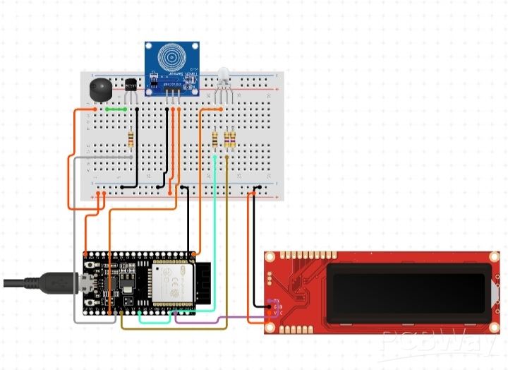
Circuit Connections with Assigned Pin Numbers
Here are the connections for each component, along with their respective assigned pin numbers:
1. LCD Connection:
VCC of LCD to 5V on ESP32
GND of LCD to GND on ESP32
SDA of LCD to GPIO 21 (I2C SDA)
SCL of LCD to GPIO 22 (I2C SCL)

2. Touch Sensor Connection:
VCC of TTP223 to 5V on ESP32
GND of TTP223 to GND on ESP32
Output of TTP223 to GPIO 23
3. RGB LED Connection:
Common Anode of RGB LED to 5V
Red Cathode to GPIO 15 through a 220Ω resistor
Green Cathode to GPIO 2 through a 220Ω resistor
Blue Cathode to GPIO 4 through a 220Ω resistor

Instructions for Uploading the Code
1. Install Arduino IDE:
Download and install the Arduino IDE from the official Arduino website.
2. Install ESP32 Board Package:
Open Arduino IDE.
Go to File -> Preferences.
In the “Additional Board Manager URLs” field, enter:
https://dl.espressif.com/dl/package_esp32_index.json
Go to Tools -> Board -> Boards Manager.
Search for "ESP32" and install the latest version.
3.Select the Board:
Go to Tools -> Board and select "ESP32 Dev Module".
4. Install LiquidCrystal_I2C Library:
Go to Sketch -> Include Library -> Manage Libraries.
Search for "LiquidCrystal I2C" and install it.
5.Upload the Code:
Connect your ESP32 board to your computer via USB cable.
Select the correct port under Tools -> Port.
Copy and paste the provided code into the Arduino IDE.
Click the Upload button (right arrow).
#include <Wire.h>
#include <LiquidCrystal_I2C.h>

#define TOUCH_PIN 23
#define BUZZER_PIN 18

LiquidCrystal_I2C lcd(0x27, 16, 2); // Adjust the address if necessary
const int dotTime = 200; // Duration for a dot signal
String morseInput = "";

// RGB LED Pins
const int redPin = 15;
const int greenPin = 2;
const int bluePin = 4;

// Morse Code Mapping
const char* morseCode[36] = {
  ".-",   // A
  "-...", // B
  "-.-.", // C
  "-..",  // D
  ".",    // E
  "..-.", // F
  "--.",  // G
  "....", // H
  "..",   // I
  ".---", // J
  "-.-",  // K
  ".-..", // L
  "--",   // M
  "-.",   // N
  "---",  // O
  ".--.", // P
  "--.-", // Q
  ".-.",  // R
  "...",  // S
  "-",    // T
  "..-",  // U
  "...-", // V
  ".--",  // W
  "-..-", // X
  "-.--", // Y
  "--..", // Z
  "-----",// 0
  ".----", // 1
  "..---", // 2
  "...--", // 3
  "....-", // 4
  ".....", // 5
  "-....", // 6
  "--...", // 7
  "---..", // 8
  "----."  // 9
};

void setup() {
  Serial.begin(115200);
  lcd.begin();
  lcd.backlight();
  pinMode(TOUCH_PIN, INPUT);
  pinMode(BUZZER_PIN, OUTPUT);
  pinMode(redPin, OUTPUT);
  pinMode(greenPin, OUTPUT);
  pinMode(bluePin, OUTPUT);
}

void loop() {
  // Record the start time when the button is pressed
  if (digitalRead(TOUCH_PIN) == HIGH) {
    delay(20); // Debounce delay
    unsigned long startTime = millis();

    while (digitalRead(TOUCH_PIN) == HIGH); // Wait until button is released

    unsigned long duration = millis() - startTime;

    if (duration < dotTime) {
      morseInput += "."; // Short press for dot
      playDotSound();
      showDotColor();
    } else {
      morseInput += "-"; // Long press for dash
      playDashSound();
      showDashColor();
    }

    lcd.clear();
    lcd.print(morseInput); // Display current Morse code input

    // Process the input after a short delay
    if (duration > 0) {
      delay(300);
      decodeMorse(morseInput);
      morseInput = ""; // Clear input after processing
    }
  }
}

void playDotSound() {
  digitalWrite(BUZZER_PIN, HIGH);
  delay(50);
  digitalWrite(BUZZER_PIN, LOW);
  delay(50);
}

void playDashSound() {
  digitalWrite(BUZZER_PIN, HIGH);
  delay(100);
  digitalWrite(BUZZER_PIN, LOW);
  delay(100);
}

void showDotColor() {
  digitalWrite(redPin, HIGH); // Show Red for Dot
  digitalWrite(greenPin, LOW);
  digitalWrite(bluePin, LOW);
  delay(300);
}

void showDashColor() {
  digitalWrite(redPin, HIGH); // Show Red for Dash
  digitalWrite(greenPin, LOW);
  delay(700);
}

void decodeMorse(String code) {
  char letter = '?'; // Default for unknown codes

  for (int i = 0; i < 36; i++) {
    if (code == morseCode[i]) {
      letter = 'A' + i; // Convert index to letter
      break;
    }
  }

  // Output the letter
  Serial.println(letter);
  lcd.clear();
  lcd.print(letter); // Display the decoded letter
}
ESP-32 Morse Code Trainer


Raspberry Pi 5 7 Inch Touch Screen IPS 1024x600 HD LCD HDMI-compatible Display for RPI 4B 3B+ OPI 5 AIDA64 PC Secondary Screen(Without Speaker)
BUY NOW


- Comments(2)
- Likes(1)
 More by Engineer

-
Programmable Mist Maker - XIAO / QT PY Extension
430 0 0 -
RadioHAT - Raspberry Pi radio development platform
333 0 1 -
-
-
-
-
ARPS-2 – Arduino-Compatible Robot Project Shield for Arduino UNO
2887 0 6 -
A Compact Charging Breakout Board For Waveshare ESP32-C3
3386 3 8 -
AI-driven LoRa & LLM-enabled Kiosk & Food Delivery System
3712 2 2


