


|
KiCADKicad
|
STM32 MINI DEVELOPMENT BOARD
In this project, the focus is the designing of an STM32 development board that has the capability of WiFi, BLE, UART, 12C, 12S, and SPI. It is a project that will be suitable to run IoT devices. The design of the project is done through the KiCAD EDA and all the production files will be available for anybody who wants to proceed to the production of the board which can be done through the PCBway
Components
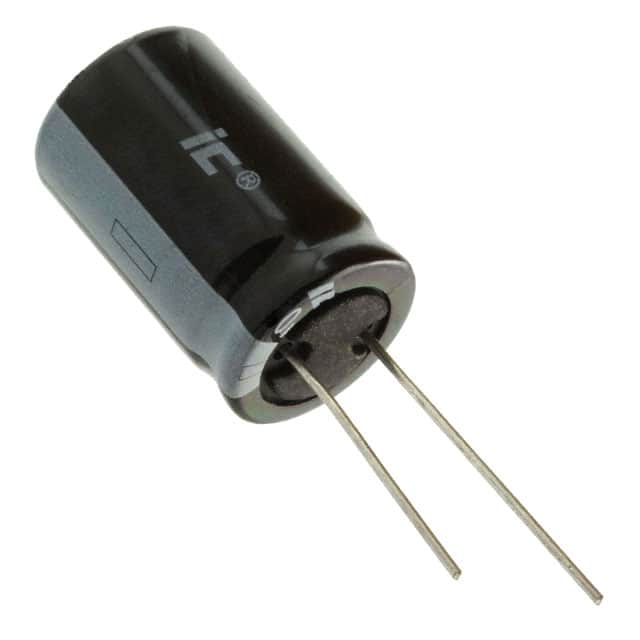
- C1, 1 470uF CP1_Small Capacitor_SMD: CP_Elec_3x5.3 Polarized capacitor, small US symbol
- C2, C3, 2 100uF C_Small Capacitor_SMD:CP_Elec_3x5. Unpolarized capacitor, a small symbol
- C4, 1 470uF CP1_Small Capacitor_SMD: CP_Elec_3x5.4 Polarized capacitor, small US symbol
- C5, C10, C11, 3 100nF C_Small Capacitor_SMD:C_0805_2012Metric Unpolarized capacitor, small symbol
- C6, C8, 2 20pF C_Small Capacitor_SMD: C_0805_2012Metric Unpolarized capacitor, small symbol
- C7, 1 10nF C_Small Capacitor_SMD: C_0805_2012Metric Unpolarized capacitor, small symbol
- C9, 1 1uF C_Small Capacitor_SMD: C_0805_2012Metric Unpolarized capacitor, small symbol
- FB1, 1 Ferrite_Bead_Small Ferrite_Bead_Small Ferrite_THT: LairdTech_28C0236-0JW-10 Ferrite bead, small symbol
- J1, J3, 2 Conn_01x12 Conn_01x12 Connector_PinHeader_1.00mm:PinHeader_1x12_P1.00mm_Vertical Generic connector, single row, 01x12, script generated (kicad-library-utils/schlub/autogenous/connector/)
- J2, 1 Conn_01x04 Conn_01x04 Connector_PinHeader_1.00mm:PinHeader_1x04_P1.00mm_Horizontal Generic connector, single row, 01x04, script generated (kicad-library-utils/schlib/autogen/connector/)
- SW1, 1 SW_Push SW_Push Fuse: Fuse_0805_2012Metric Push button switch, generic, two pins
- U1, 1 AP1117-33 AP1117-33 Package_TO_SOT_SMD:SOT-223-3_TabPin2 1A Low Dropout regulator, positive, 3.3V fixed output, SOT-223
- U2, 1 STM32F031K6 STM32F031K6 Package_QFP:LQFP-32_5x5mm_P0.5mm
- Y1, 1 Crystal_Small Crystal_Small Crystal: Crystal_SMD_HC49-SD Two-pin crystal, a small symbol
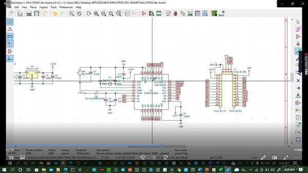
Designing of the Schematic
- Fire up KiCAD and proceed to new then new project and fire up the schematic window and start placing the components as shown below.
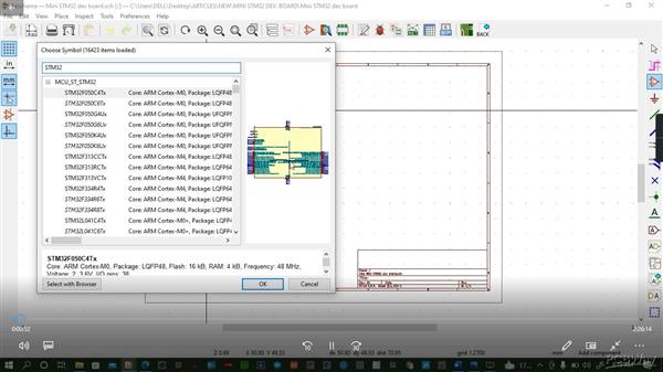
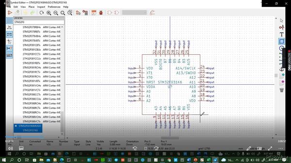
Check for the STM32-WROOM symbol and place it. If the symbol is not existing you can create your symbol as shown below
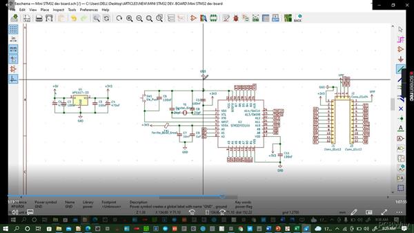
Place all other components as you do the wire connections to end up with the schematic shown below: In the schematic, we have done the connection of the STM32 as per the datasheet available on most component vendors' sites. We have also done a power supply schematic to power our STM32 at 3V3.
Go to annotation and annotate your schematic to give every component a unique label automatically instead of doing it manually. For example in the schematic above all capacitors have a label of C? but we can give each capacitor a label let us say C1, C2, and so on through annotation.
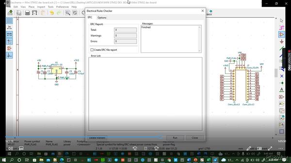
Check the electrical rules to ensure that the circuit is good and has complete functionality. Ensure there are zero earnings and errors before you proceed to the next step
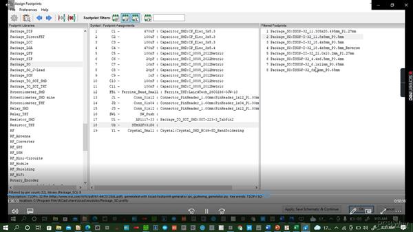
Addition of footprints to your schematics then generate the netlists, save and proceed to PCB layout
PCB Layout
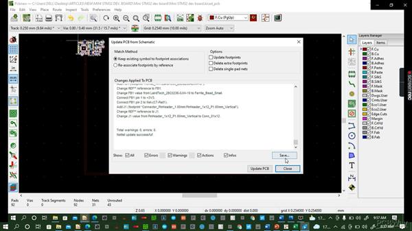
On opening the PCB layout windows, the first step is updating the footprints.
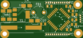
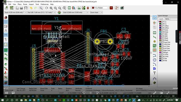
After updating the netlist you start arranging your components in preparation for routing. The components after being placed will give you an outlook shown below:
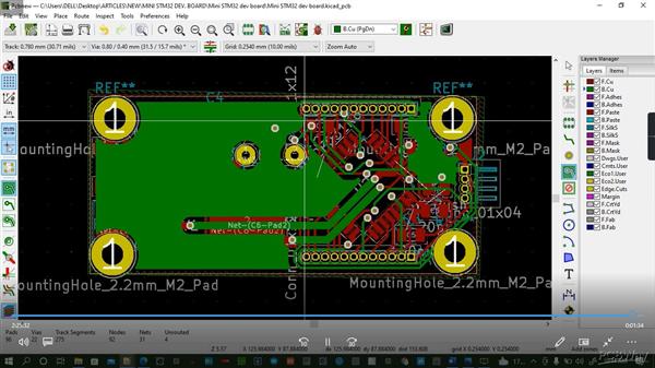
Here, after nicely arranging the components as per the schematic, the routing process starts and at the end of the routing you end up with a product similar to this:
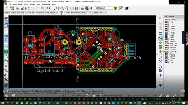
Add the edge cut to give your board a desired shape from your heart.
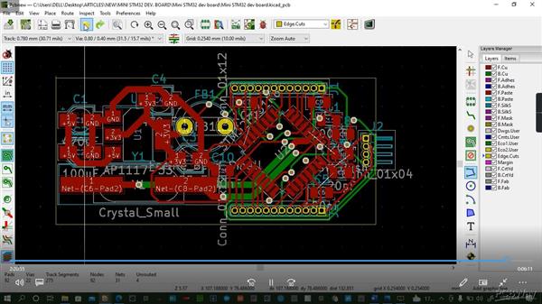
Add copper pores to your board to separate the ground from the active areas.
3D Generation.
Finally, you can convert your routed PCB into a 3D view to have your nice board as shown below.

And this marks the end of our tutorial on how to do the mini SR=TM32 board design using KiCAD EDA.

STM32 MINI DEVELOPMENT BOARD
*PCBWay community is a sharing platform. We are not responsible for any design issues and parameter issues (board thickness, surface finish, etc.) you choose.


Raspberry Pi 5 7 Inch Touch Screen IPS 1024x600 HD LCD HDMI-compatible Display for RPI 4B 3B+ OPI 5 AIDA64 PC Secondary Screen(Without Speaker)
BUY NOW


- Comments(0)
- Likes(0)
More by Simon Mugo
-
 High Power Three Channel LED Driver
IntroductionI have been thinking about how to drive RGB LED patterns most simply. In my day-to-day r...
High Power Three Channel LED Driver
IntroductionI have been thinking about how to drive RGB LED patterns most simply. In my day-to-day r...
-
 433 MHz Radio Frequency Transmitter Module
IntroductionTwo devices can communicate with each other using radio frequencies and using an RF tran...
433 MHz Radio Frequency Transmitter Module
IntroductionTwo devices can communicate with each other using radio frequencies and using an RF tran...
-
 Customized Servo Motor Driver Board
IntroductionServo motors, also called rotary or linear actuators, are designed for minimal control o...
Customized Servo Motor Driver Board
IntroductionServo motors, also called rotary or linear actuators, are designed for minimal control o...
-
 Arduino Customized L298M Dual Motor Driver Module
IntroductionThe Arduino Customized L298M Dual Motor Driver Module is designed to handle high-power D...
Arduino Customized L298M Dual Motor Driver Module
IntroductionThe Arduino Customized L298M Dual Motor Driver Module is designed to handle high-power D...
-
 Overvoltage Protection Board
PrecautionBefore making use of the circuit in this design project, ensure that you first set the var...
Overvoltage Protection Board
PrecautionBefore making use of the circuit in this design project, ensure that you first set the var...
-
 Automatic Residential Lighting System Board Based on AT89C51
In our day-to-day activities, we often don't remember to switch off or on the lights in our rooms. T...
Automatic Residential Lighting System Board Based on AT89C51
In our day-to-day activities, we often don't remember to switch off or on the lights in our rooms. T...
-
 The Energy Saving Bulb Board
The traditional incandescent bulb is an energy waster and it should be removed off shelves. My new t...
The Energy Saving Bulb Board
The traditional incandescent bulb is an energy waster and it should be removed off shelves. My new t...
-
 ESP8266 MINI TEST BOARD
Design Of The SchematicThe schematic design is done in KiCAD. The process starts with finding the da...
ESP8266 MINI TEST BOARD
Design Of The SchematicThe schematic design is done in KiCAD. The process starts with finding the da...
-
 POWER SUPPLY FOR THE ESP8266
ESP8266 is a microchip of low cost that is produced by a company by the name of ESPPRESSIF stems. It...
POWER SUPPLY FOR THE ESP8266
ESP8266 is a microchip of low cost that is produced by a company by the name of ESPPRESSIF stems. It...
-
 1N4148 INCOPORATING 741 IC TEMEPERATURE SENSOR
Creating a simple temperature sensor using a diode (1N4148) and an operational amplifier (741 IC) is...
1N4148 INCOPORATING 741 IC TEMEPERATURE SENSOR
Creating a simple temperature sensor using a diode (1N4148) and an operational amplifier (741 IC) is...
-
 TSL25911 Light Sensor
IntroductionWe interact with different intensities and strengths of light in our daily activities. T...
TSL25911 Light Sensor
IntroductionWe interact with different intensities and strengths of light in our daily activities. T...
-
 SIM800 GPS module
ElevatorThis project demonstrates how you can develop various GPS/ GPRS and SMS capability developme...
SIM800 GPS module
ElevatorThis project demonstrates how you can develop various GPS/ GPRS and SMS capability developme...
-
 nRF51822 Mini Evaluation Board
IntroductionDemand for development and evaluation boards the world over has increased. Due to such d...
nRF51822 Mini Evaluation Board
IntroductionDemand for development and evaluation boards the world over has increased. Due to such d...
-
 Customized LM393D Soil Moisture Sensor Board
ElevatorThe project is good at converting analog signals from the soil to digital signals for soil m...
Customized LM393D Soil Moisture Sensor Board
ElevatorThe project is good at converting analog signals from the soil to digital signals for soil m...
-
 PAM8403 Amplifier Module
IntroductionThis is a simple project for improving your musical or audio entertainment by powering y...
PAM8403 Amplifier Module
IntroductionThis is a simple project for improving your musical or audio entertainment by powering y...
-
 741 IC Bass Booster
IntroductionIn this project, we are going to design a bass booster circuit using the 741 IC. This is...
741 IC Bass Booster
IntroductionIn this project, we are going to design a bass booster circuit using the 741 IC. This is...
-
 LM317 AND LM337 ADJUSTABLE POWER SUPPLY CIRCUIT BOARD
IntroductionThe LM317/LM337 symmetrical power supply circuit is an electronic setup for meeting the ...
LM317 AND LM337 ADJUSTABLE POWER SUPPLY CIRCUIT BOARD
IntroductionThe LM317/LM337 symmetrical power supply circuit is an electronic setup for meeting the ...
-
 230V AC to 1.5V DC PCB for Your Application
IntroductionA power management integrated circuit (PMIC) is utilized to supply the necessary power t...
230V AC to 1.5V DC PCB for Your Application
IntroductionA power management integrated circuit (PMIC) is utilized to supply the necessary power t...
-
Programmable Mist Maker - XIAO / QT PY Extension
247 0 0 -
RadioHAT - Raspberry Pi radio development platform
269 0 1 -
-
-
-
-
ARPS-2 – Arduino-Compatible Robot Project Shield for Arduino UNO
2827 0 6 -
A Compact Charging Breakout Board For Waveshare ESP32-C3
3331 3 8 -
AI-driven LoRa & LLM-enabled Kiosk & Food Delivery System
3629 2 2


