


ESP32-Based 3D Printed Fish Feeder RC Board with ESP-Now Controller
The original plan for this project was to create a fun RC Paddle Boat. However, during the project, I came up with the idea of adding a fish feeder. This means that besides enjoying a ride around the lake, the boat can also be used as a bait board for fishing, and can deliver food and medicine in pellet size needed by fish to otherwise inaccessible areas like Mangrove.
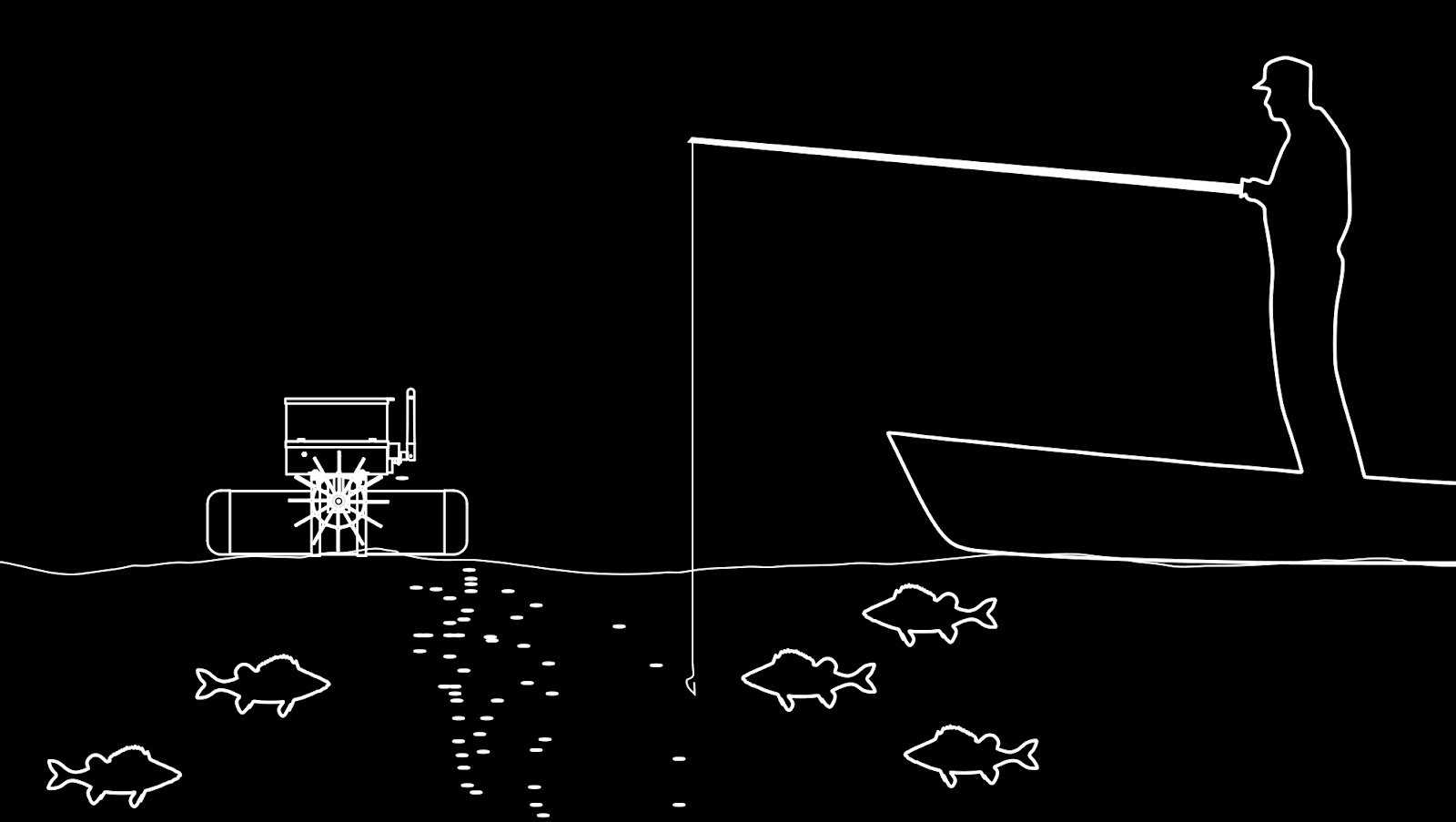
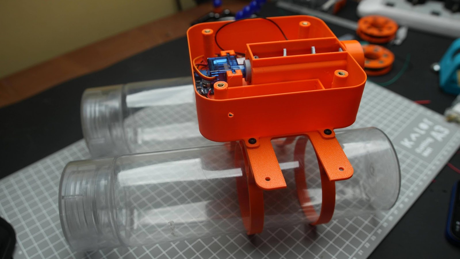
The RC controller and the Boat communicate using the ESP-NOW protocol, eliminating the need for a separate radio controller circuit and reducing the complexity and cost of the construction. In my test, I achieved a range of around 200m (line of sight). Additionally, the boat stays afloat with the help of two water bottles.
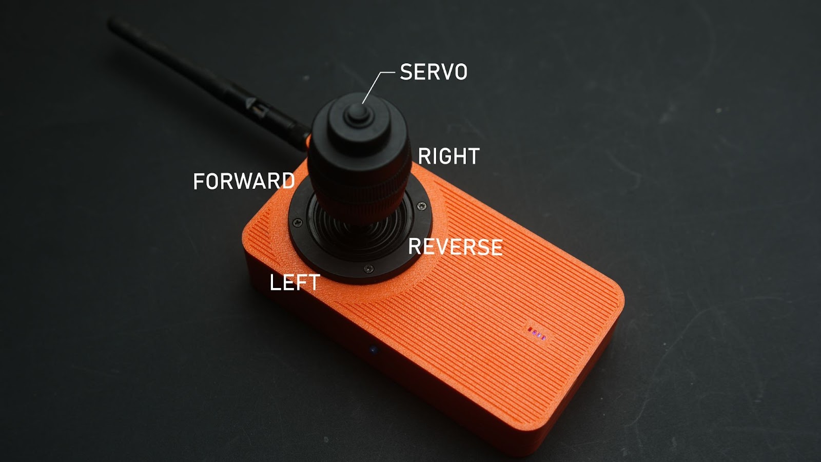
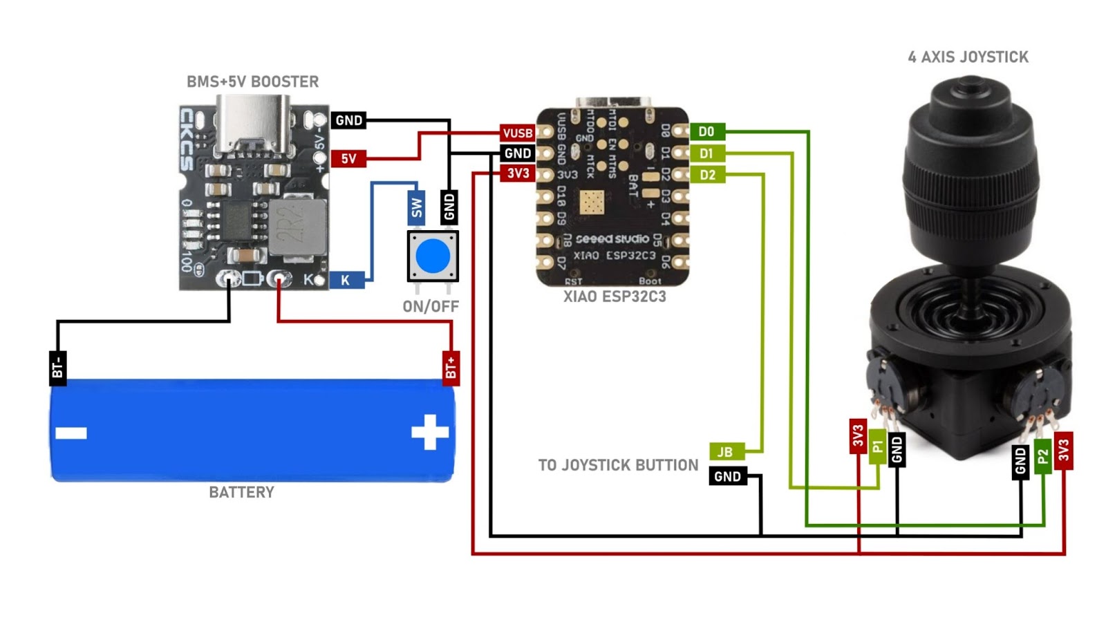
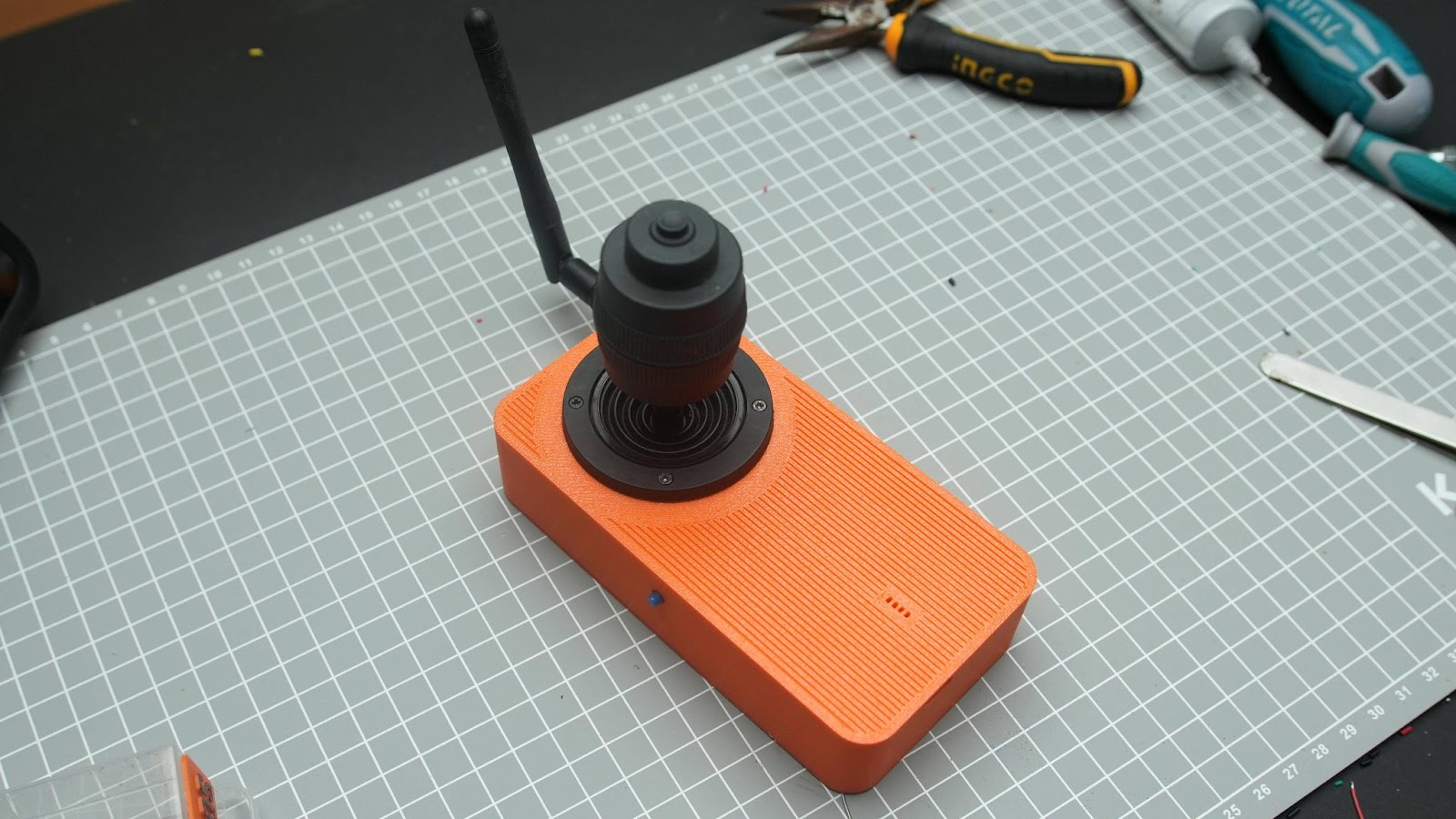
I also build an RC controller for this. you can control the movement of the boat using a single joystick also you can drop the payload by pressing the pushbutton on top of the joystick. you do not need any pairing for RX and TX it will done automatically. you can switch on the TX by pressing the push button on the side. You can also see the battery indicator on the top. TX is rechargeable through USBC
Supplies

Receiver parts
- 8*M3 x 10mm
- 4*m3 x15mm
- 12* M3 nut
- 4*m4 x10mm
- 4*m4 x nut
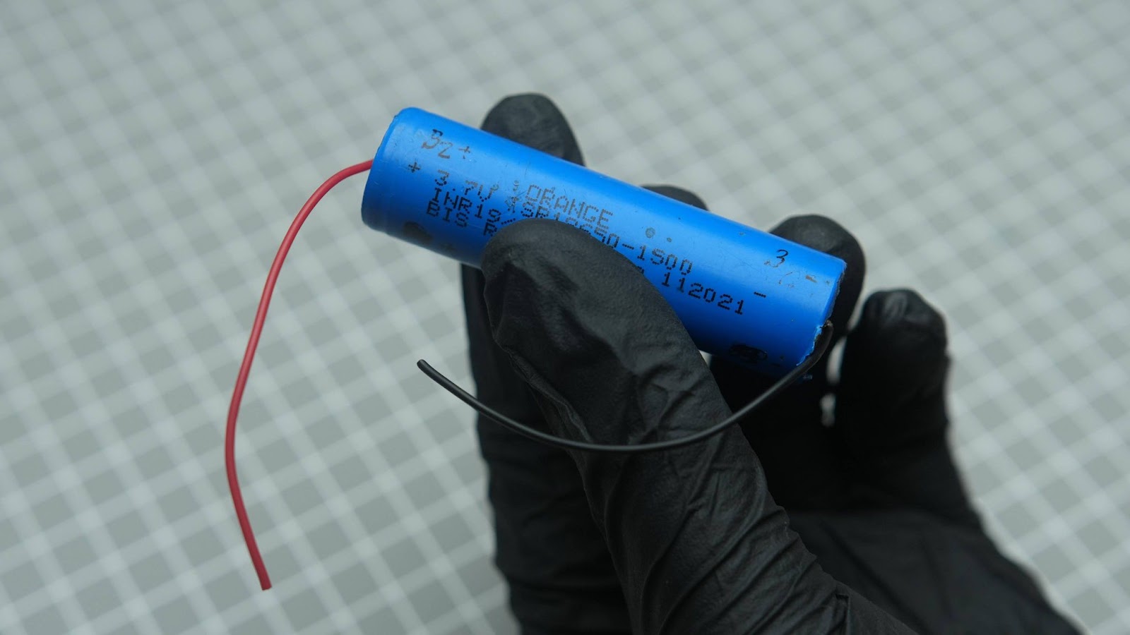
- 2*18650 Battery 2500mah
- 2*To pin JST XH connectors male and female (2.54MM PITCH)
- MT3608 voltage booster
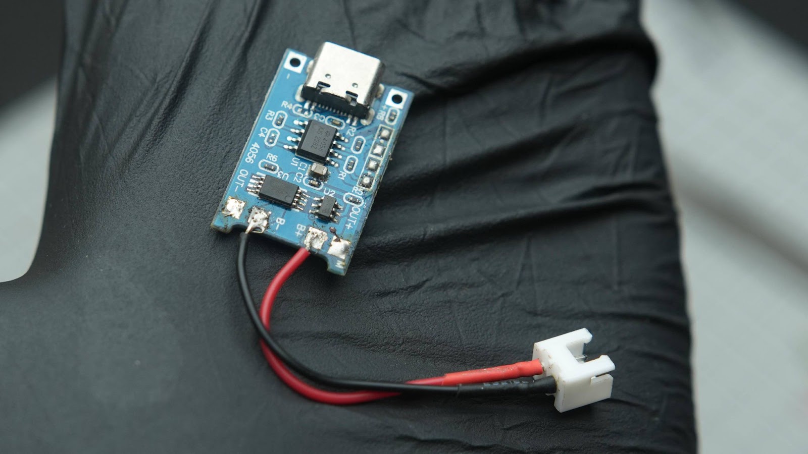
- BMS 5v booster
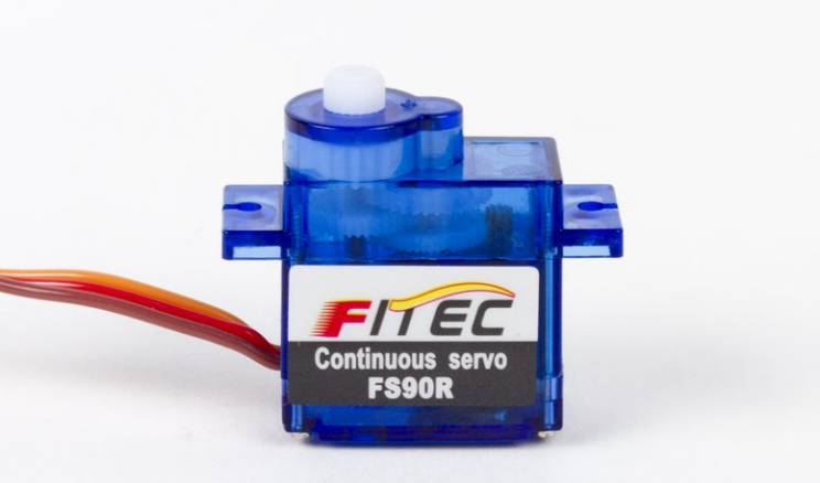
- 360-degree servo
- 4*M4 6mm Knurled Threaded Insert
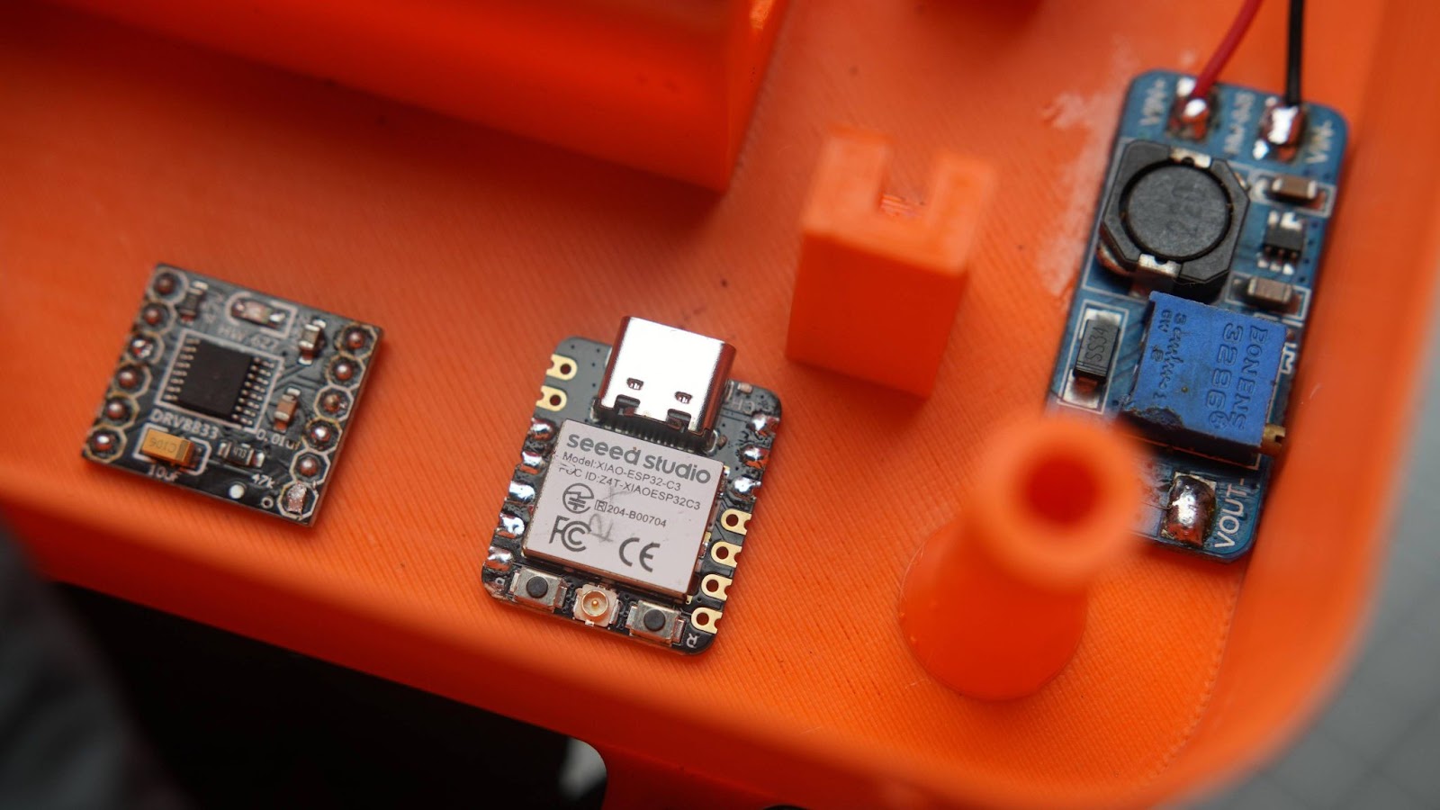
- DRV8833 motor driver
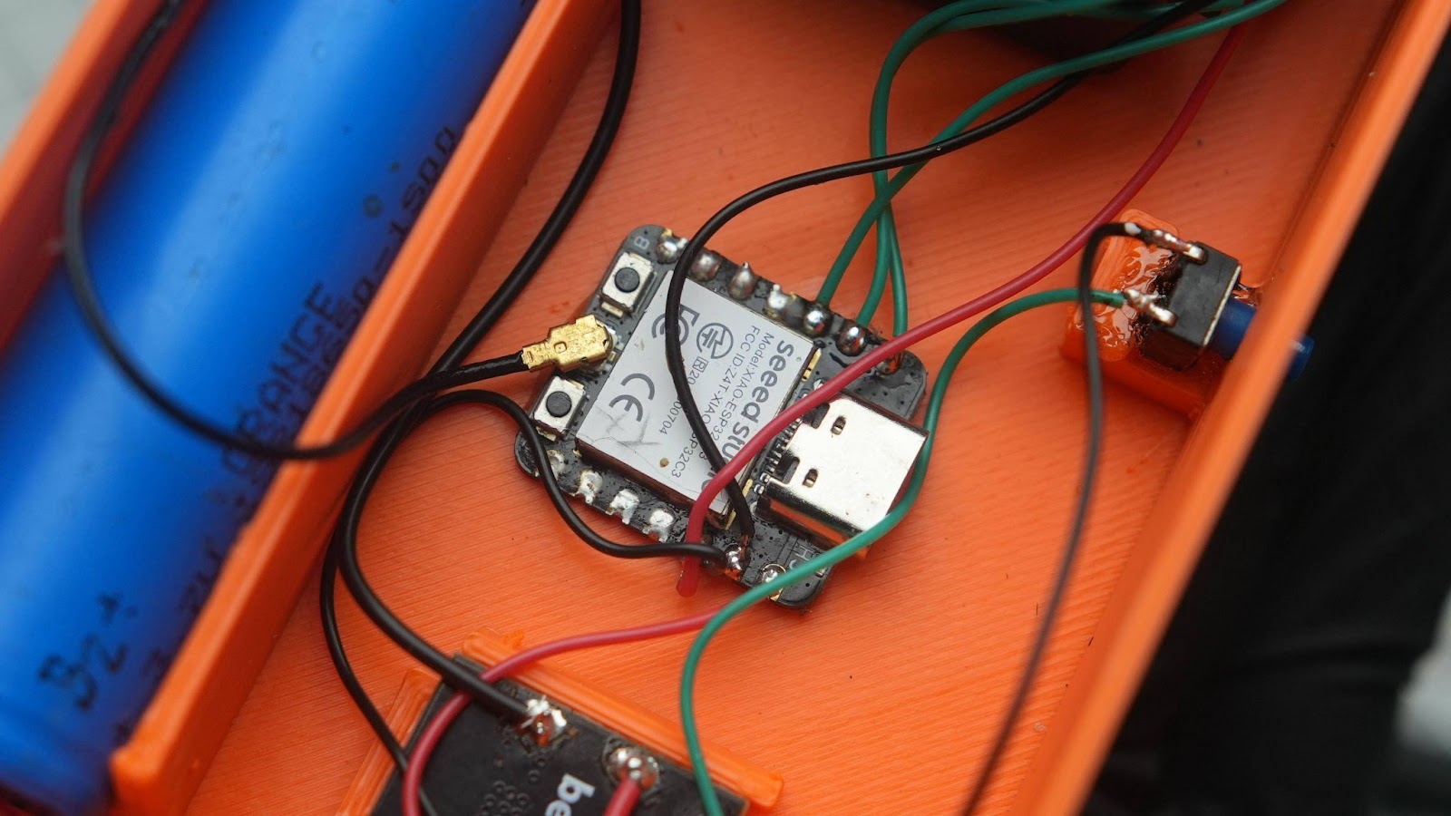
- Seeed Studio XIAO ESP32C3
- 2*300 RPM L-Shape BO Motor (couldn't find international shipping )
- 2.4ghz antenna
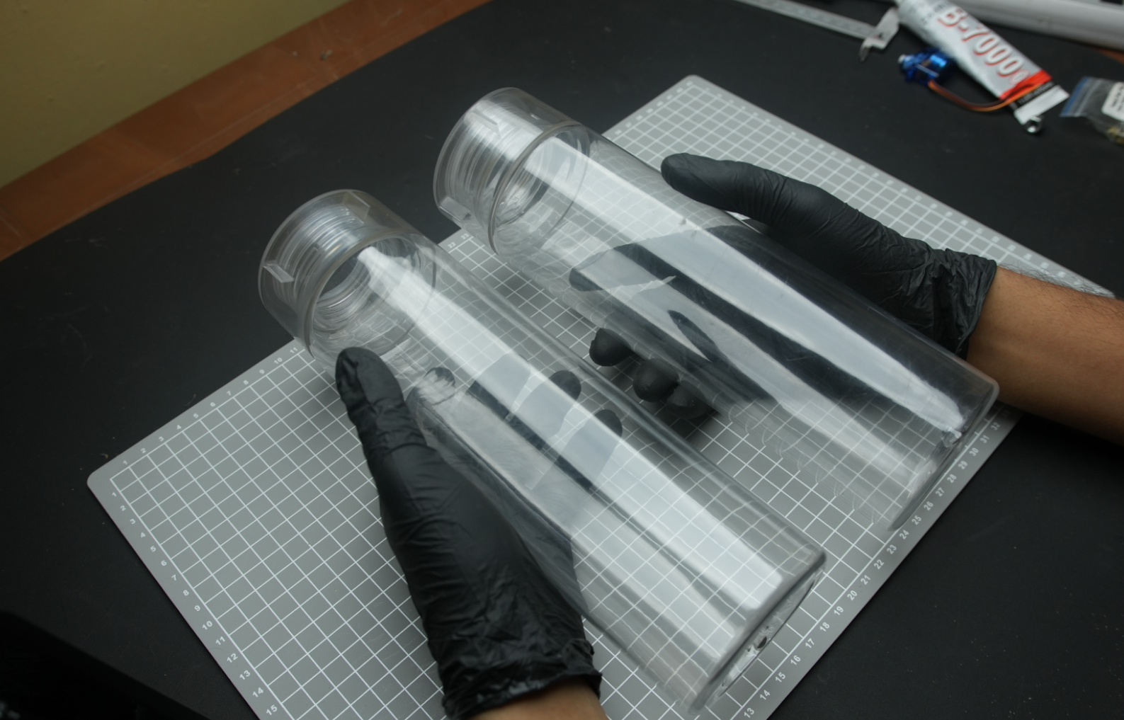
- 2*water bottles
- Heat Shrink Tubing kit
Transmitter parts
- 18650 Battery 2500mah
- Push button
- Seeed Studio XIAO ESP32C3
- BMS 5v booster
- 2.4ghz antenna
- 4 axis joystick
We are not using ordinary servo motors for this project. We need a 360-degree servo for this build. Currently, I'm using a modified 90° servo. This video helped me learn how to mod it. However, there's no need to modify the 360-degree servo; it is available in the market. I have attached a link to it in the part list.
For this project, I used a 1L water bottle with a 3-inch diameter. If you can't find one like this, you can also use a PVC pipe with both ends closed. A simple redesign of the floater holder will enable you to adapt this build to any other size of similar-looking water bottles.
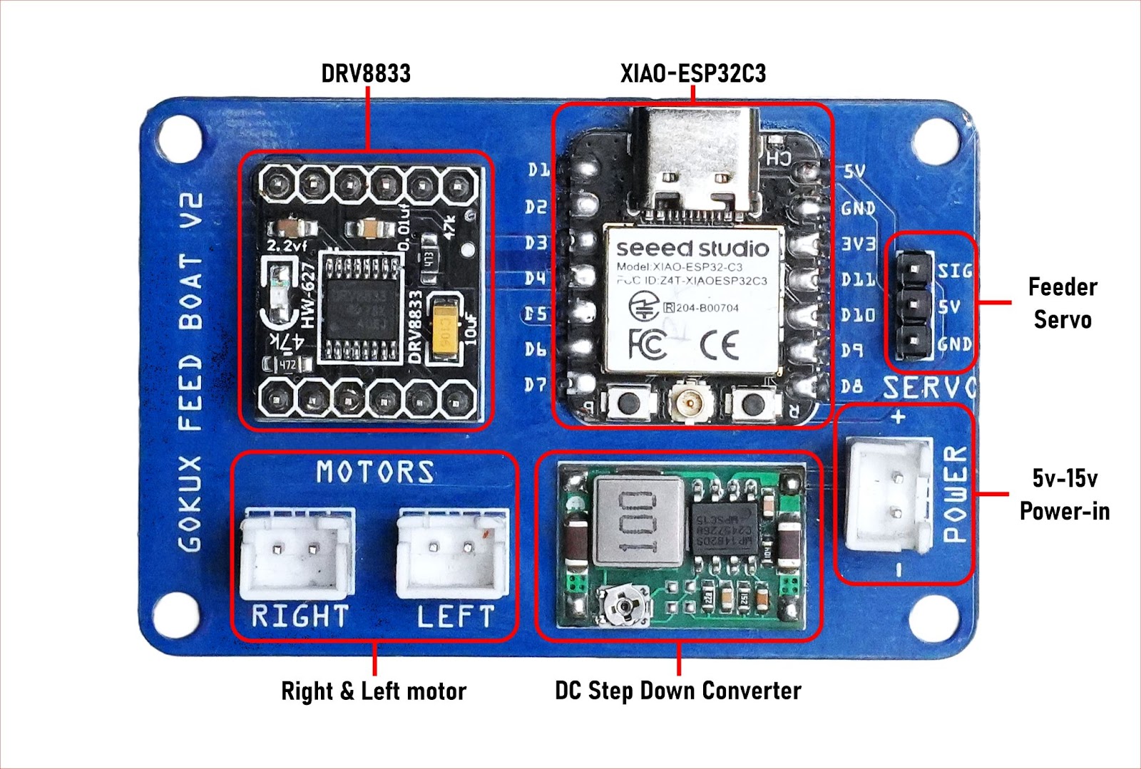
PCB Update for This Project
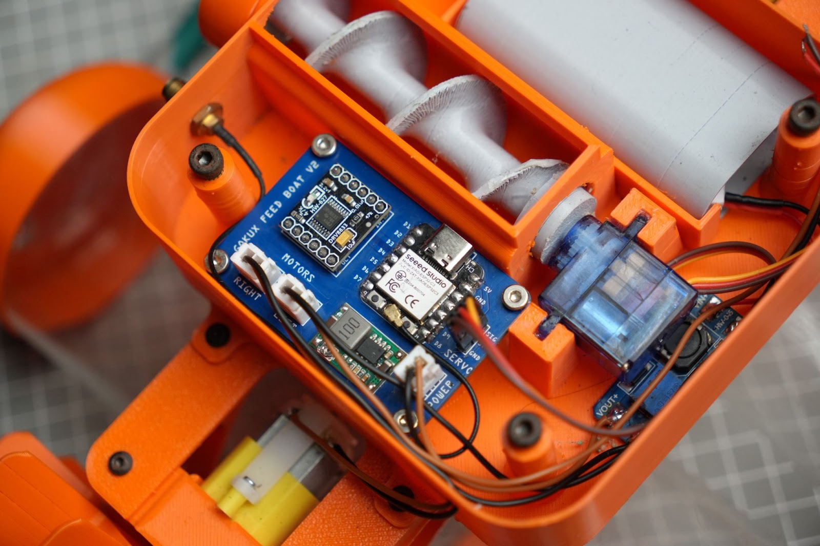
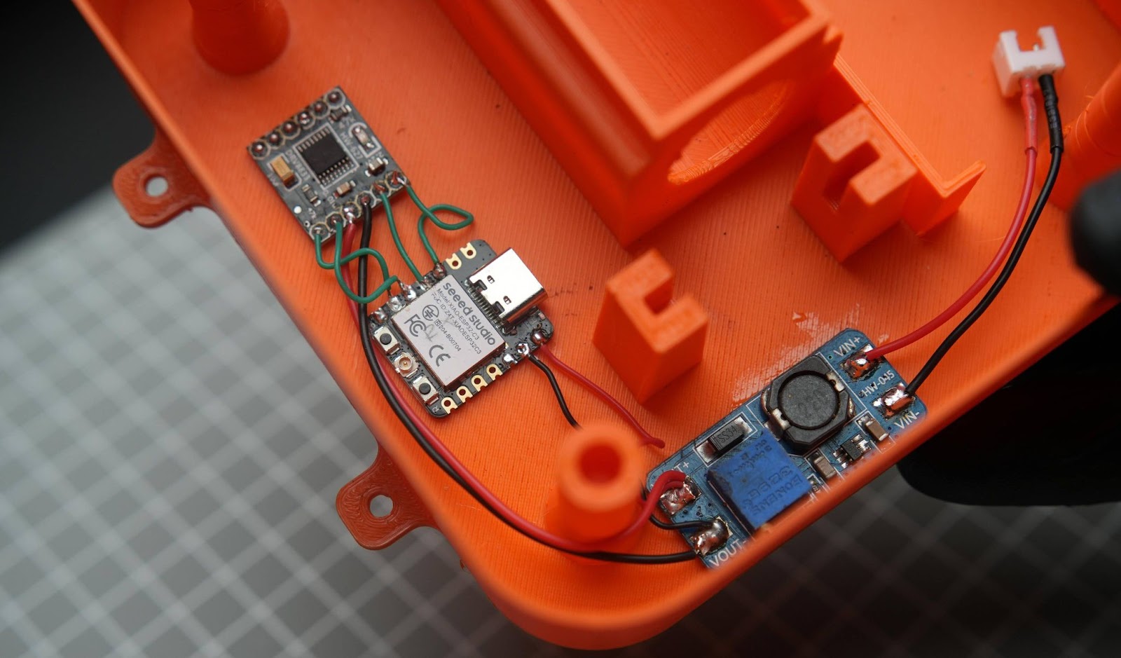
To simplify the project's complexity, I have designed a PCB main board specifically for the receiver section. A 5V regulator is included to power the Xiao ESP32-C3, allowing you to increase the voltage in the main boost converter, enhancing the motor's speed and power. You can find the Gerber file attached to this step.
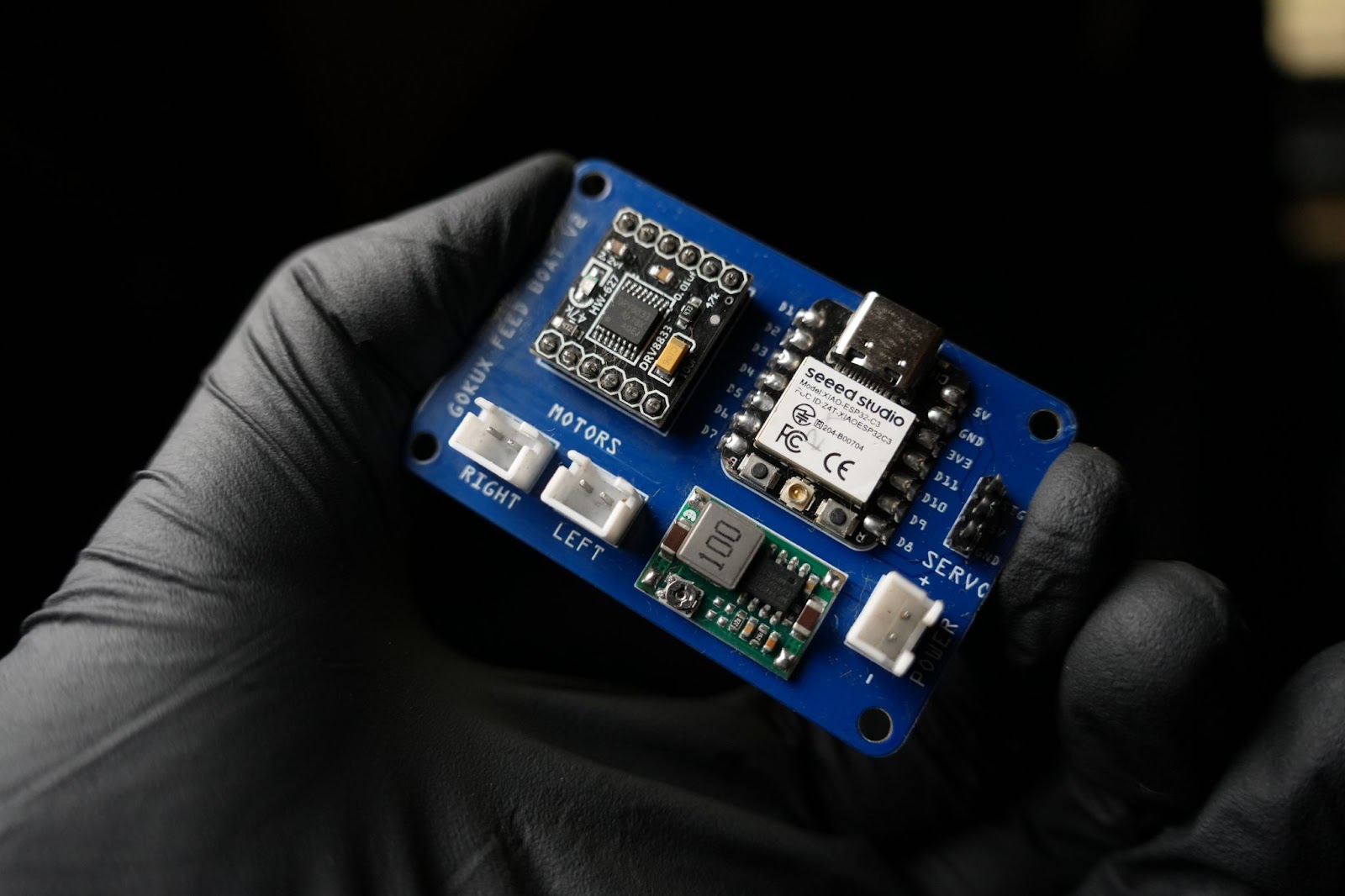
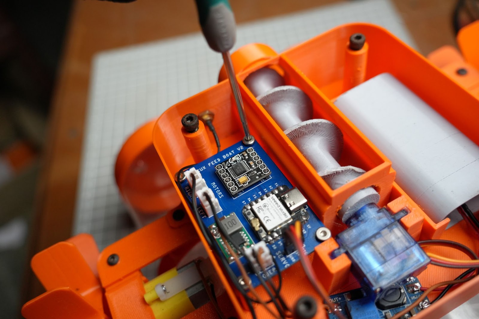
Additionally, the main body has been updated with PCB holder points, where you can use M3 screws to secure the PCB in place. We are now using JST connectors for both the motor output and the main power input. Furthermore, you can connect the servo directly to the PCB using header pins, eliminating the need to cut any wires. The DRV8833 and Mini 360 step-down converter can be soldered to the PCB using male header pins I
so we need some additional parts for this project
Male header pins
3* male and female JST 2.54mm XH connectors
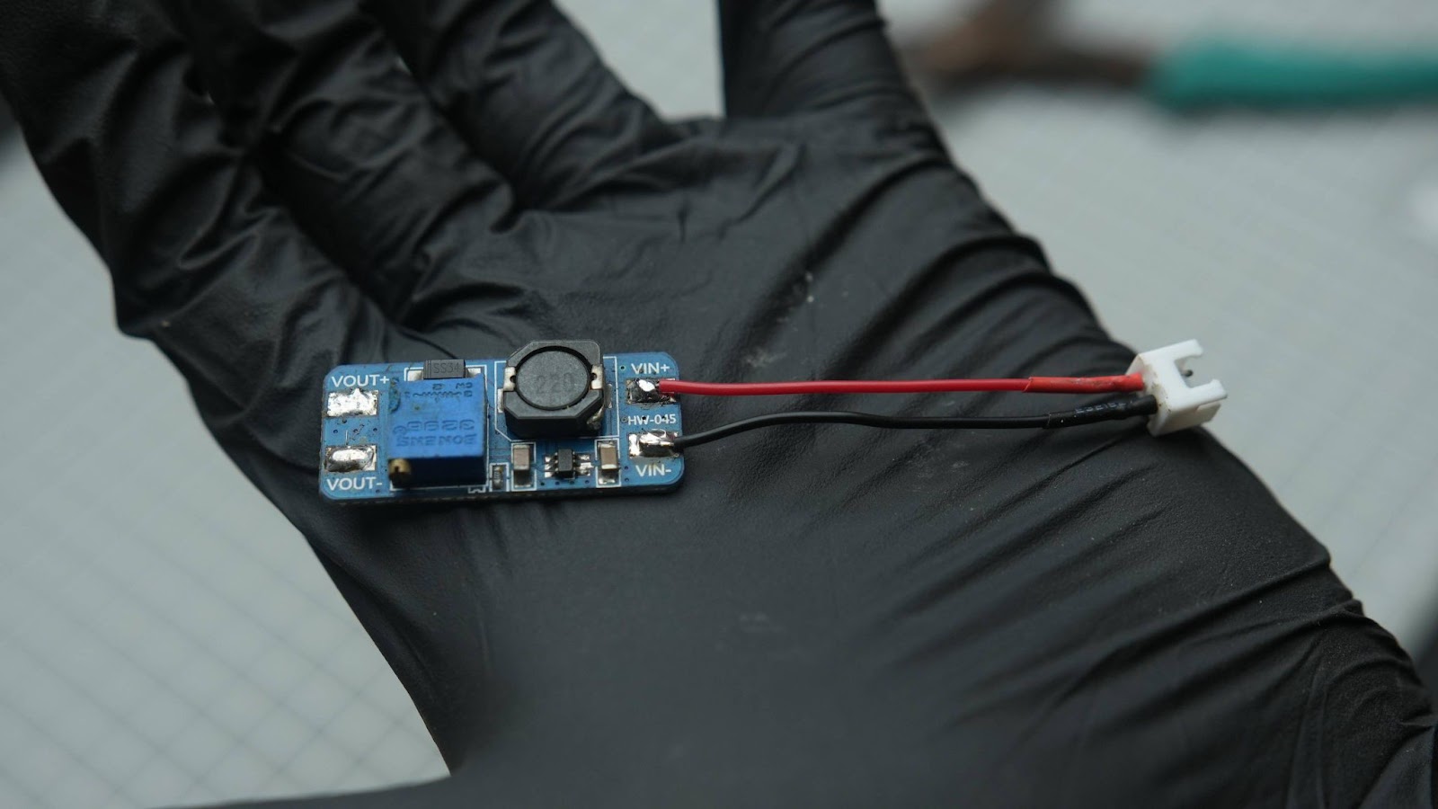
Mini 360 Step-Down Buck Converter Power Module
Step 1: 3D Printing

I designed the object in parts due to its complex nature, so we will need to assemble it after 3D printing. I used orange PLA and grey PLA. 3D printed all models in my anycubic printer. In 0.2mm layer height and 30% infill
Also please note that you had to print several STL files multiple Times
Floater clamp X4
Floater end cap X4
Motor clamp X2
Motor holder X2
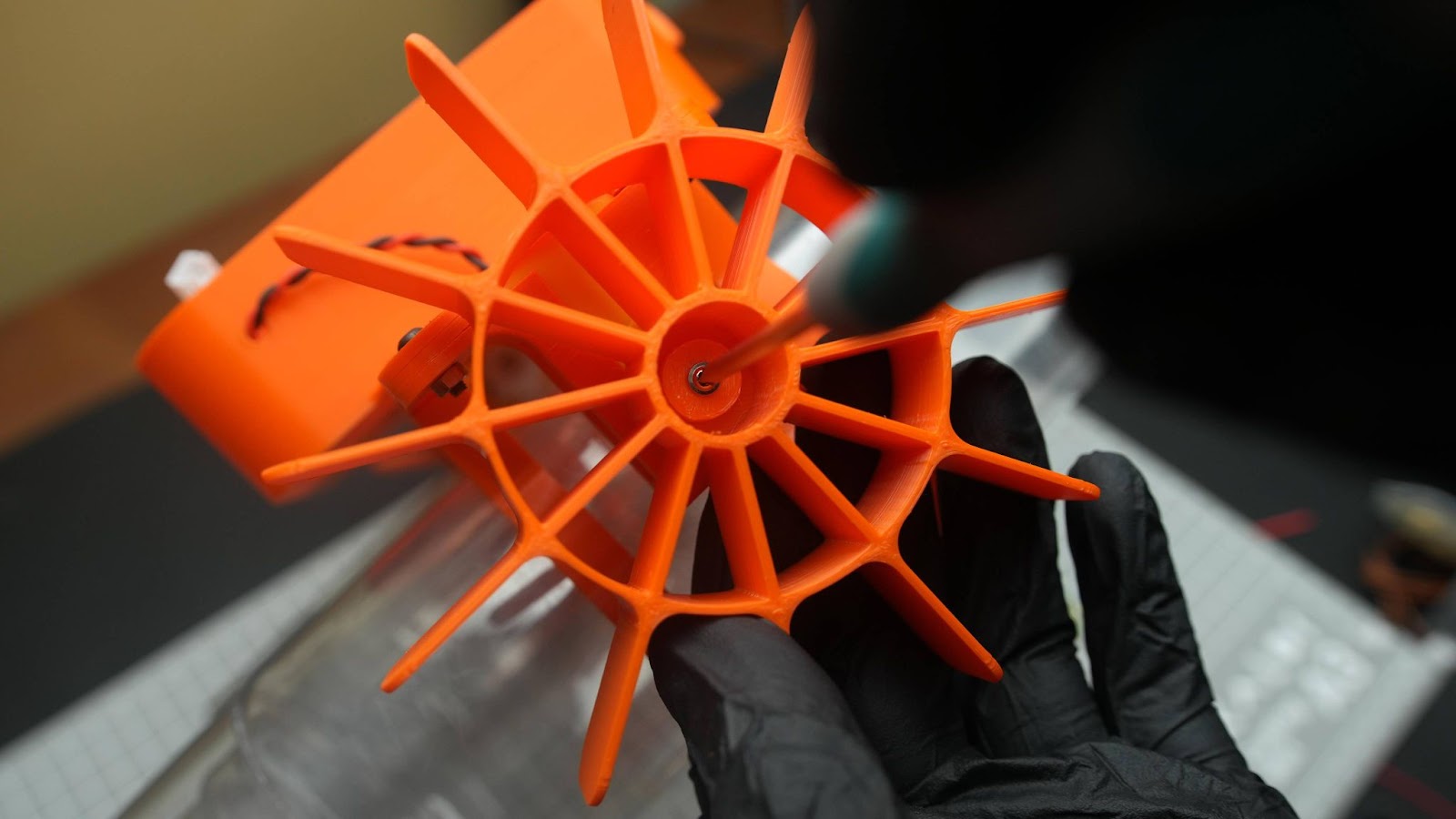
Wheel X2
Step 2: Finding the MAC Address of Your XIAO ESP32C3

We are using the ESP-NOW protocol for communication between the transmitter (TX) and receiver (RX). For this, the transmitter (TX) needs to know the unique MAC address of the RX ESP32. You will need to run the following code on your ESP32C3 receiver (XIAO) to find its MAC address. After running this program, the MAC address will be displayed on the serial monitor.
My MAC address is 64:E8:33:8A:22:54
Code for finding the MAC address
#include <WiFi.h> #include <esp_wifi.h> void readMacAddress(){ uint8_t baseMac[6]; esp_err_t ret = esp_wifi_get_mac(WIFI_IF_STA, baseMac); if (ret == ESP_OK) { Serial.printf("%02x:%02x:%02x:%02x:%02x:%02x\n", baseMac[0], baseMac[1], baseMac[2], baseMac[3], baseMac[4], baseMac[5]); } else { Serial.println("Failed to read MAC address"); } } void setup(){ Serial.begin(115200); WiFi.mode(WIFI_STA); WiFi.STA.begin(); Serial.print("[DEFAULT] ESP32 Board MAC Address: "); readMacAddress(); } void loop(){ }
Step 3: Flashing Program the Code
Before uploading the code we need to enter the MAC address of our receiver which is 64:E8:33:8A:22:54 for me we need to add a 0x before it ,
Then it will be 0x64,0xE8,0x33,0x8A,0x22,0x54
Put that in this line of the code
// MAC address of the receiver uint8_t receiverAddress[] = {0x64, 0xE8, 0x33, 0x8A, 0x22, 0x54};
Here is the full code for the TX
#include<Arduino.h> #include<esp_now.h> #include<WiFi.h> // Define pins for Xiao ESP32C3 #define JOYSTICK_X_PIN 0 // ADC1 channel 1 (GPIO 0) #define JOYSTICK_Y_PIN 1 // ADC1 channel 2 (GPIO 1) #define SERVO_BUTTON_PIN 2 // Thresholds for joystick movement #define JOYSTICK_THRESHOLD 100 // Structure to hold the message data typedefstructstruct_message { int xAxis; int yAxis; bool servo; } struct_message; struct_message message; // MAC address of the receiver uint8_t receiverAddress[] = {0x64, 0xE8, 0x33, 0x8A, 0x22, 0x54}; voidsetup(){ Serial.begin(115200); // Initialize pins pinMode(JOYSTICK_X_PIN, INPUT); pinMode(JOYSTICK_Y_PIN, INPUT); pinMode(SERVO_BUTTON_PIN, INPUT_PULLUP); // Initialize WiFi in station mode WiFi.mode(WIFI_STA); // Init ESP-NOW if (esp_now_init() != ESP_OK) { Serial.println("Error initializing ESP-NOW"); return; } // Register peer esp_now_peer_info_t peerInfo; memcpy(peerInfo.peer_addr, receiverAddress, 6); peerInfo.channel = 0; peerInfo.encrypt = false; // Add peer if (esp_now_add_peer(&peerInfo) != ESP_OK) { Serial.println("Failed to add peer"); return; } } voidloop(){ // Read joystick values int xValue = analogRead(JOYSTICK_X_PIN); int yValue = analogRead(JOYSTICK_Y_PIN); // Check for significant movement message.xAxis = (abs(xValue - 2048) > JOYSTICK_THRESHOLD) ? xValue : 2048; message.yAxis = (abs(yValue - 2048) > JOYSTICK_THRESHOLD) ? yValue : 2048; // Read button state message.servo = !digitalRead(SERVO_BUTTON_PIN); // Send message via ESP-NOW esp_now_send(receiverAddress, (uint8_t *)&message, sizeof(message)); // Short delay delay(100); }
RX code
#include<Arduino.h> #include<esp_now.h> #include<WiFi.h> #include<ESP32Servo.h> // Motor driver pins #define MOTOR_A1 2 #define MOTOR_A2 3 #define MOTOR_B1 4 #define MOTOR_B2 5 // Servo pin #define SERVO_PIN 6 Servo myServo; // Structure to hold the message data typedefstructstruct_message { int xAxis; int yAxis; bool servo; } struct_message; struct_message message; voidmoveForward(){ digitalWrite(MOTOR_A1, HIGH); digitalWrite(MOTOR_A2, LOW); digitalWrite(MOTOR_B1, HIGH); digitalWrite(MOTOR_B2, LOW); } voidmoveBackward(){ digitalWrite(MOTOR_A1, LOW); digitalWrite(MOTOR_A2, HIGH); digitalWrite(MOTOR_B1, LOW); digitalWrite(MOTOR_B2, HIGH); } voidturnLeft(){ digitalWrite(MOTOR_A1, LOW); digitalWrite(MOTOR_A2, HIGH); digitalWrite(MOTOR_B1, HIGH); digitalWrite(MOTOR_B2, LOW); } voidturnRight(){ digitalWrite(MOTOR_A1, HIGH); digitalWrite(MOTOR_A2, LOW); digitalWrite(MOTOR_B1, LOW); digitalWrite(MOTOR_B2, HIGH); } voidstopMoving(){ digitalWrite(MOTOR_A1, LOW); digitalWrite(MOTOR_A2, LOW); digitalWrite(MOTOR_B1, LOW); digitalWrite(MOTOR_B2, LOW); } // Callback function to receive data voidOnDataRecv(constesp_now_recv_info_t *recv_info, constuint8_t *incomingData, int len){ memcpy(&message, incomingData, sizeof(message)); } voidsetup(){ Serial.begin(115200); // Initialize motor driver pins pinMode(MOTOR_A1, OUTPUT); pinMode(MOTOR_A2, OUTPUT); pinMode(MOTOR_B1, OUTPUT); pinMode(MOTOR_B2, OUTPUT); // Initialize servo myServo.attach(SERVO_PIN); // Initialize WiFi in station mode WiFi.mode(WIFI_STA); // Init ESP-NOW if (esp_now_init() != ESP_OK) { Serial.println("Error initializing ESP-NOW"); return; } // Register receive callback esp_now_register_recv_cb(OnDataRecv); } voidloop(){ // Handle movement based on joystick values if (message.yAxis < 1500) { moveForward(); } elseif (message.yAxis > 2500) { moveBackward(); } elseif (message.xAxis < 1500) { turnLeft(); } elseif (message.xAxis > 2500) { turnRight(); } else { stopMoving(); } // Handle servo activation if (message.servo) { myServo.write(90); // Move servo to 90 degrees } else { myServo.write(0); // Move servo back to 0 degrees } }
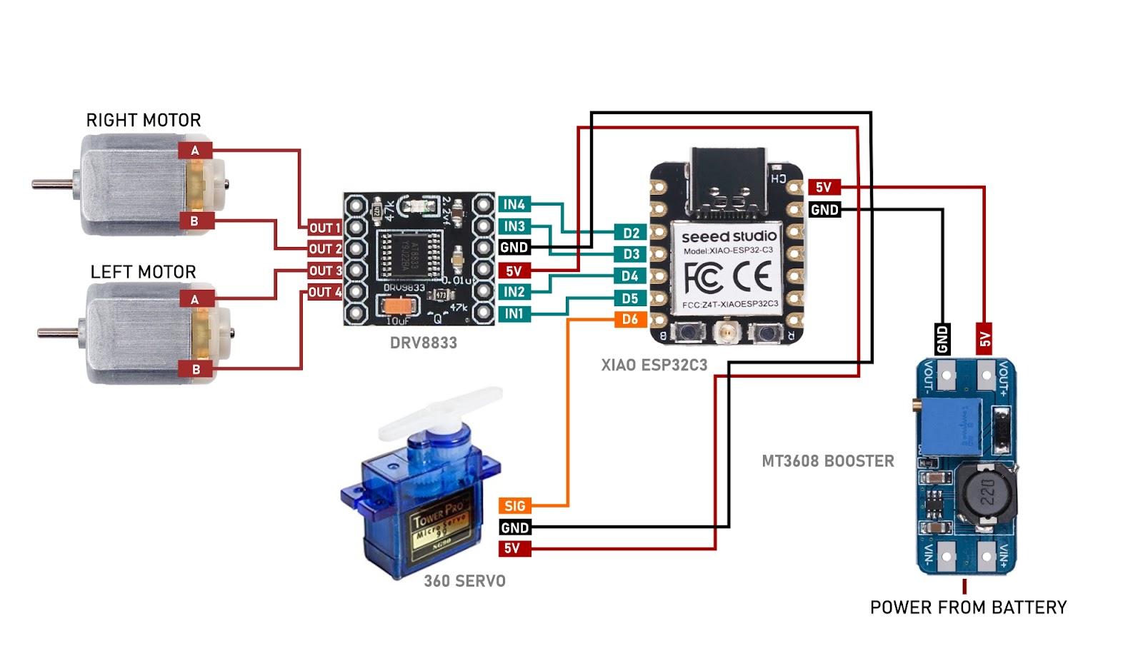
Step 5: Wiring Diagram of Transmitter and Rover
Wiring diagram of TX
Wiring diagram of RX
Step 5: Voltage Setting on MT3608

Before assembling we need to preset the voltage on MT3608, if you buy a new module you need to turn the potentiometer around 20 times or more in a counterclockwise position and then once you get the regulated voltage at the output you can use the module. Connect your battery to VIN+ and VIN- and set the voltage to 5v. measure it from the OUT+ and OUT- using a multimeter after that remove the battery input
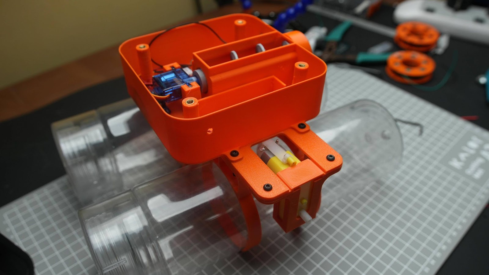
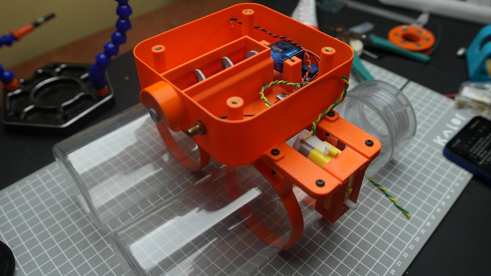
Step 6: Rover Assembly
6.1
Connect a female JST connector into the input on MT3608. Which needs to be at least 5CM in length make sure the left side of the JST is VIN+ and the right side VIN-
6.2
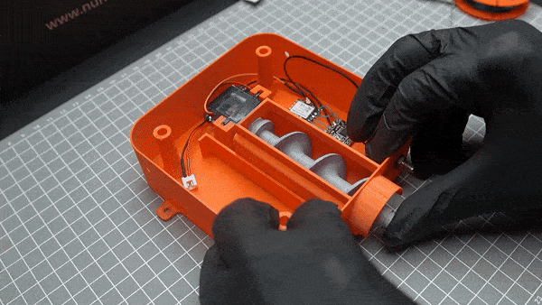
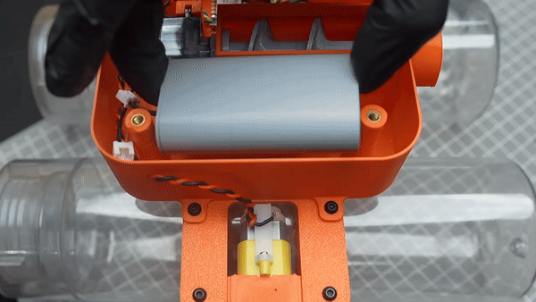
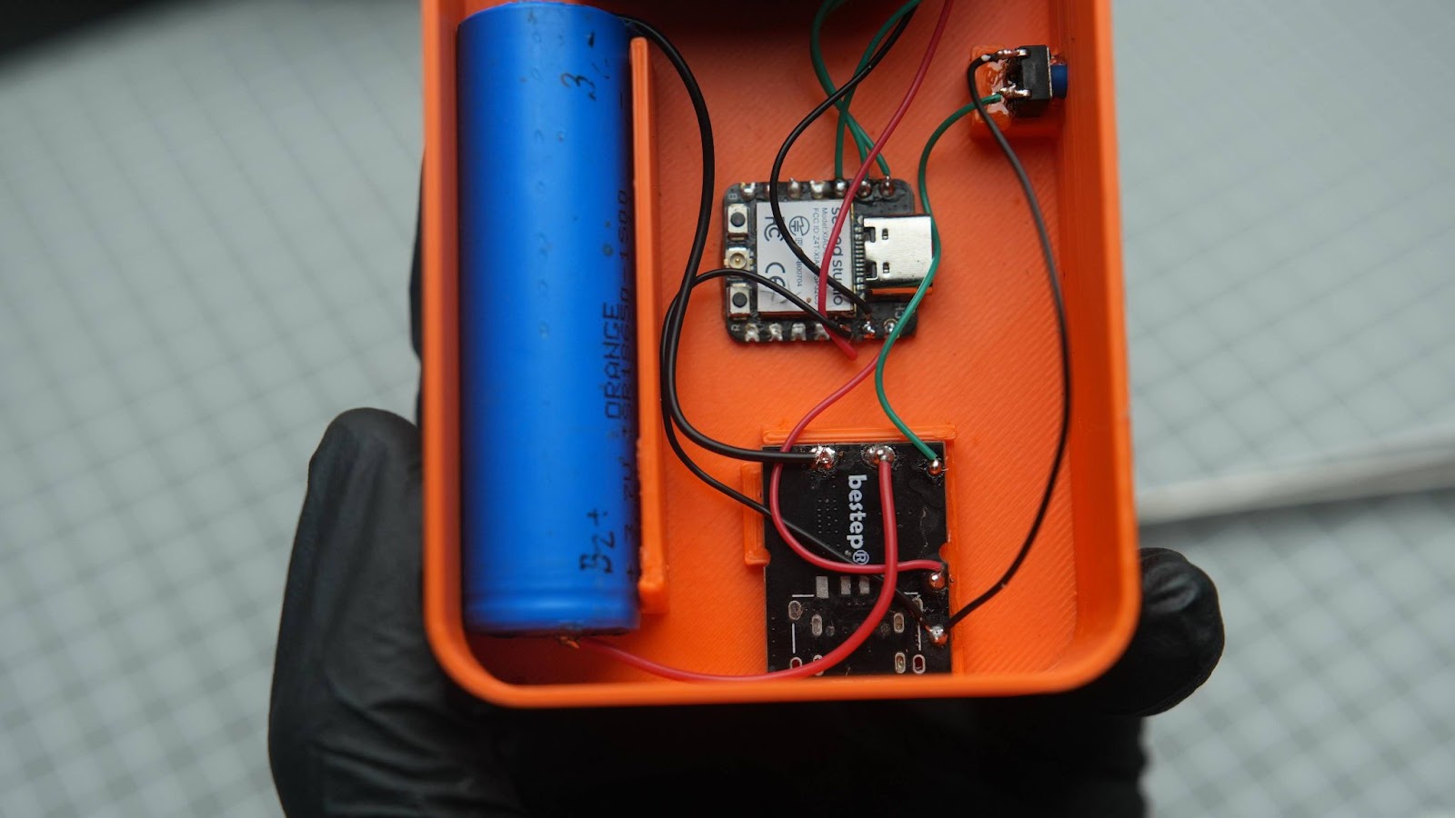
Glue the XIAO, motor driver and MT3608 into the main body
6.3
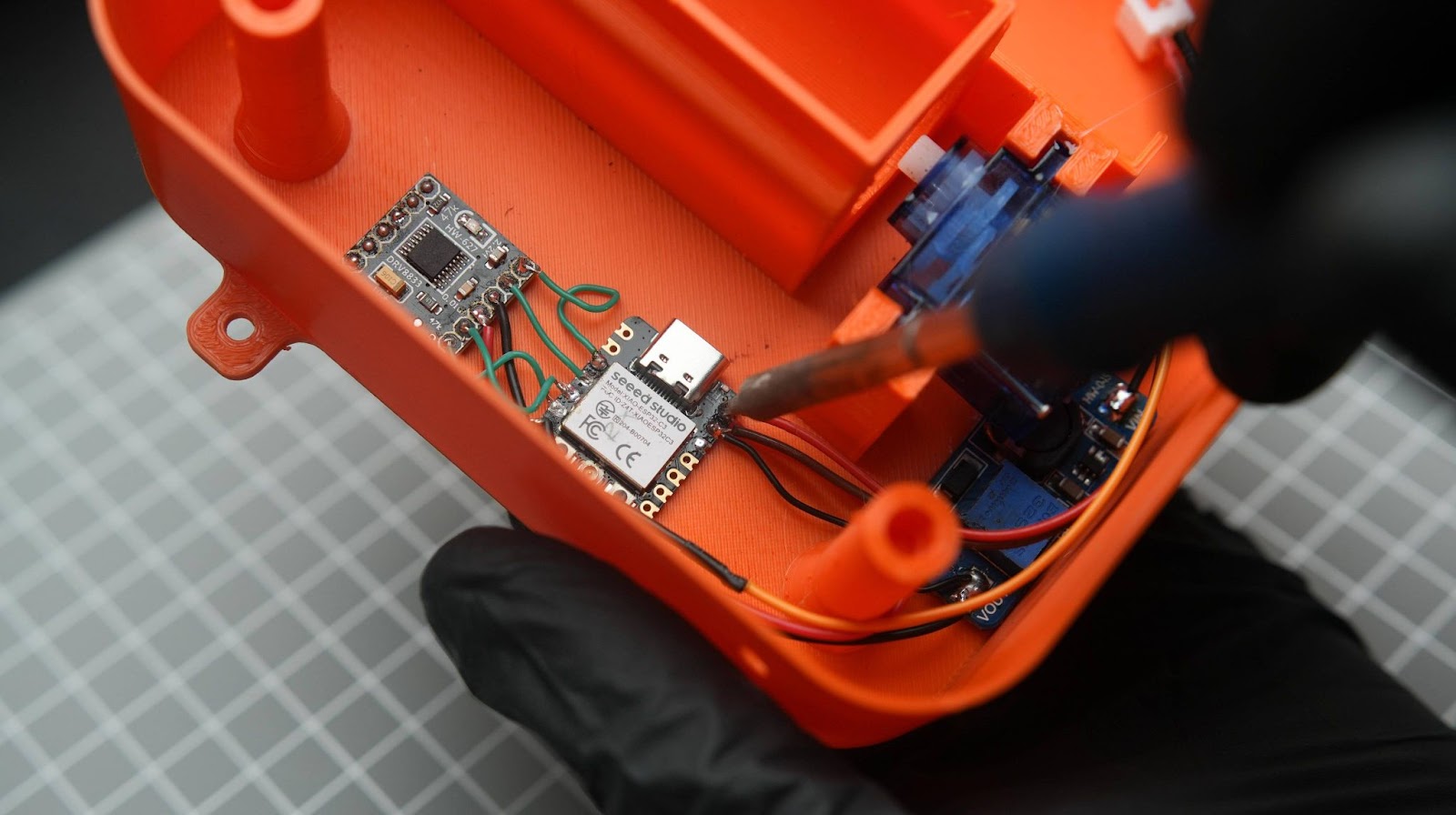
Solder and connect all wires between XIAO, motor driver and the MT3608
6.4
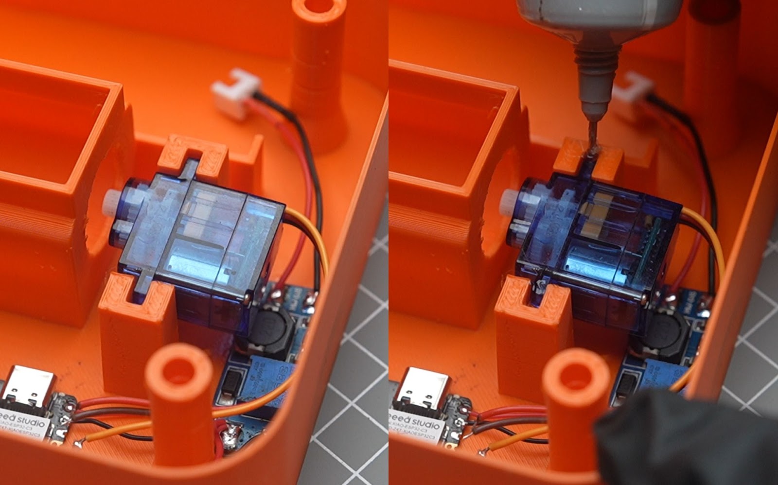
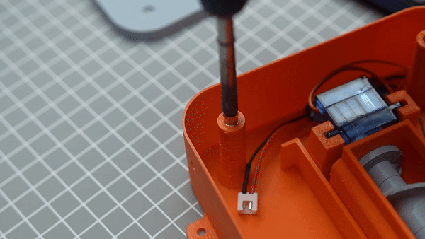
Insert the servo into the 3d printed slot and solder the wires into Xiao
6.5
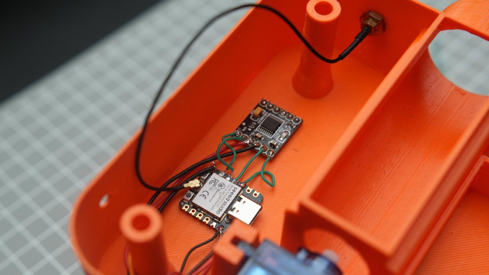
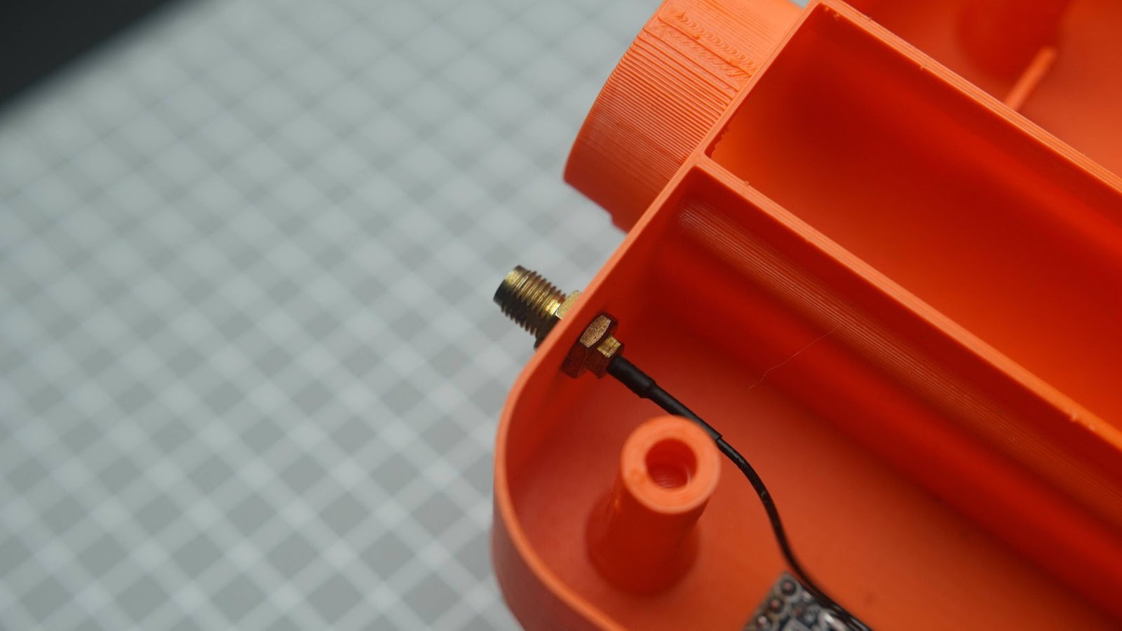
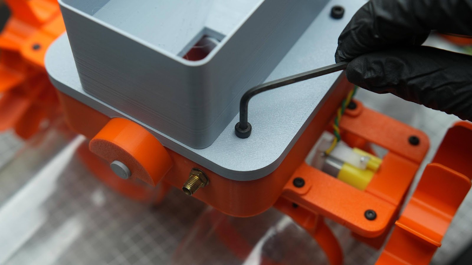
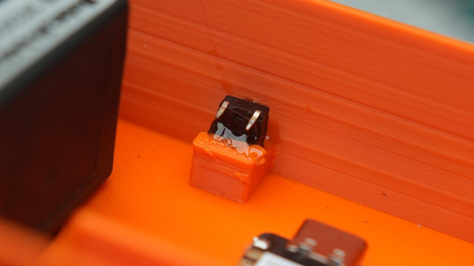
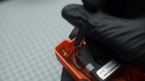
Connect the antenna port into the XIAO and another connecter to the hole on the side wall. thigh it using a nose plier
6.6
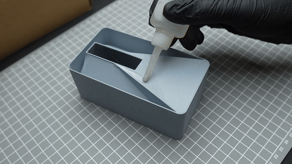
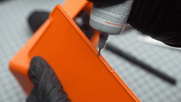
Connect the screw to the servo shaft and secure it with a screw holder. Attach the screw holder using super glue.
6.7
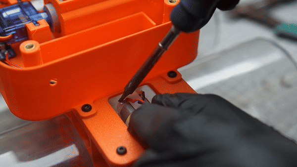
Install the M4 nut insert using a soldering iron into the 3d printer hole
Do the same thing in all 3 positions
6.8
Glue the holder into the top cap
6.9
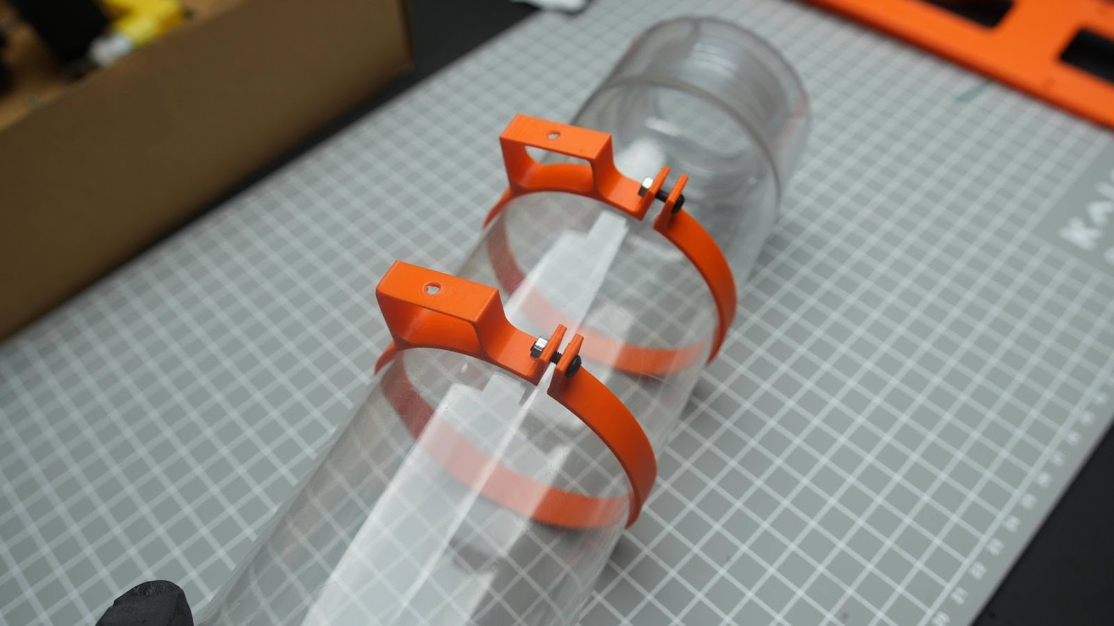
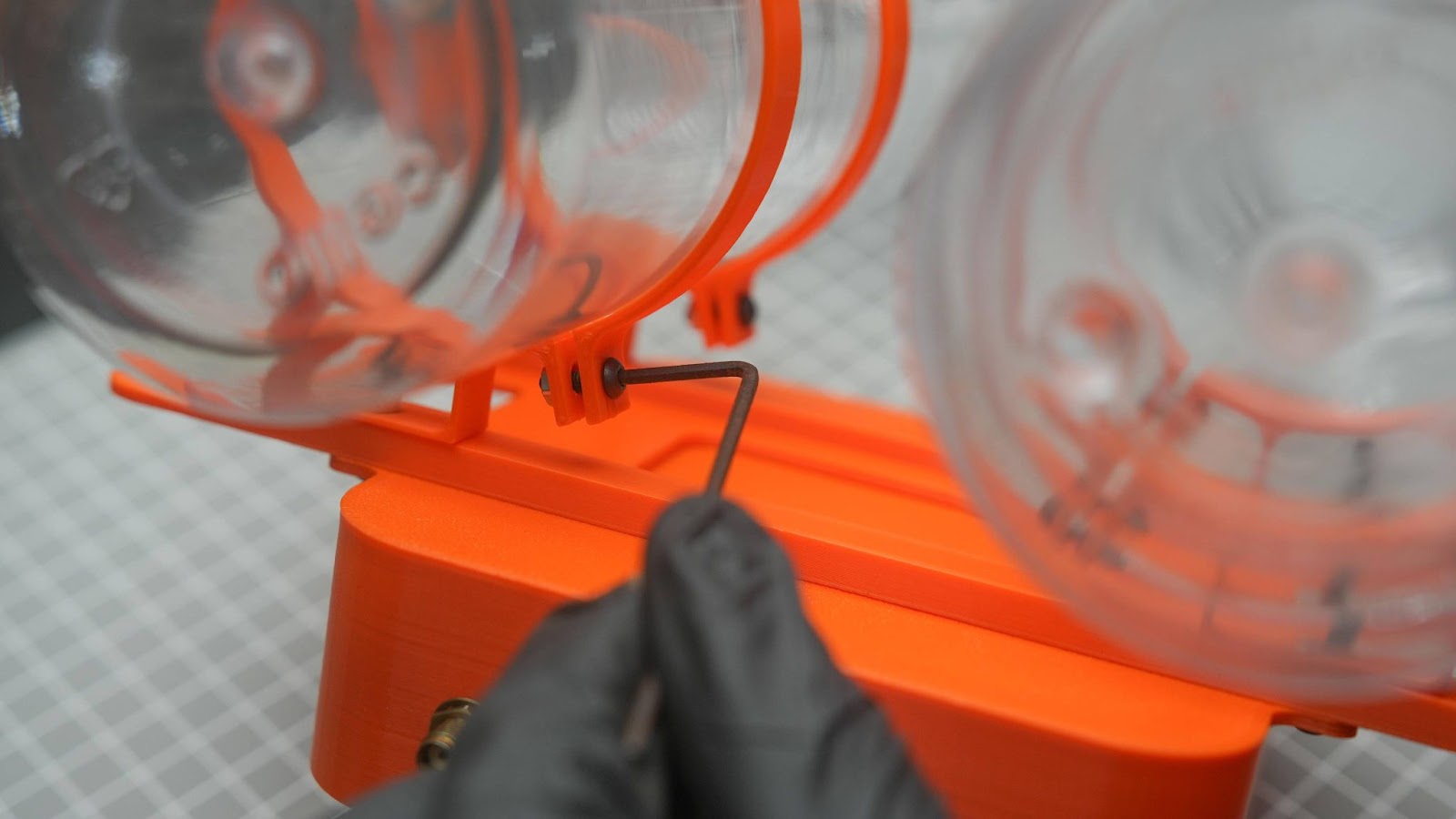
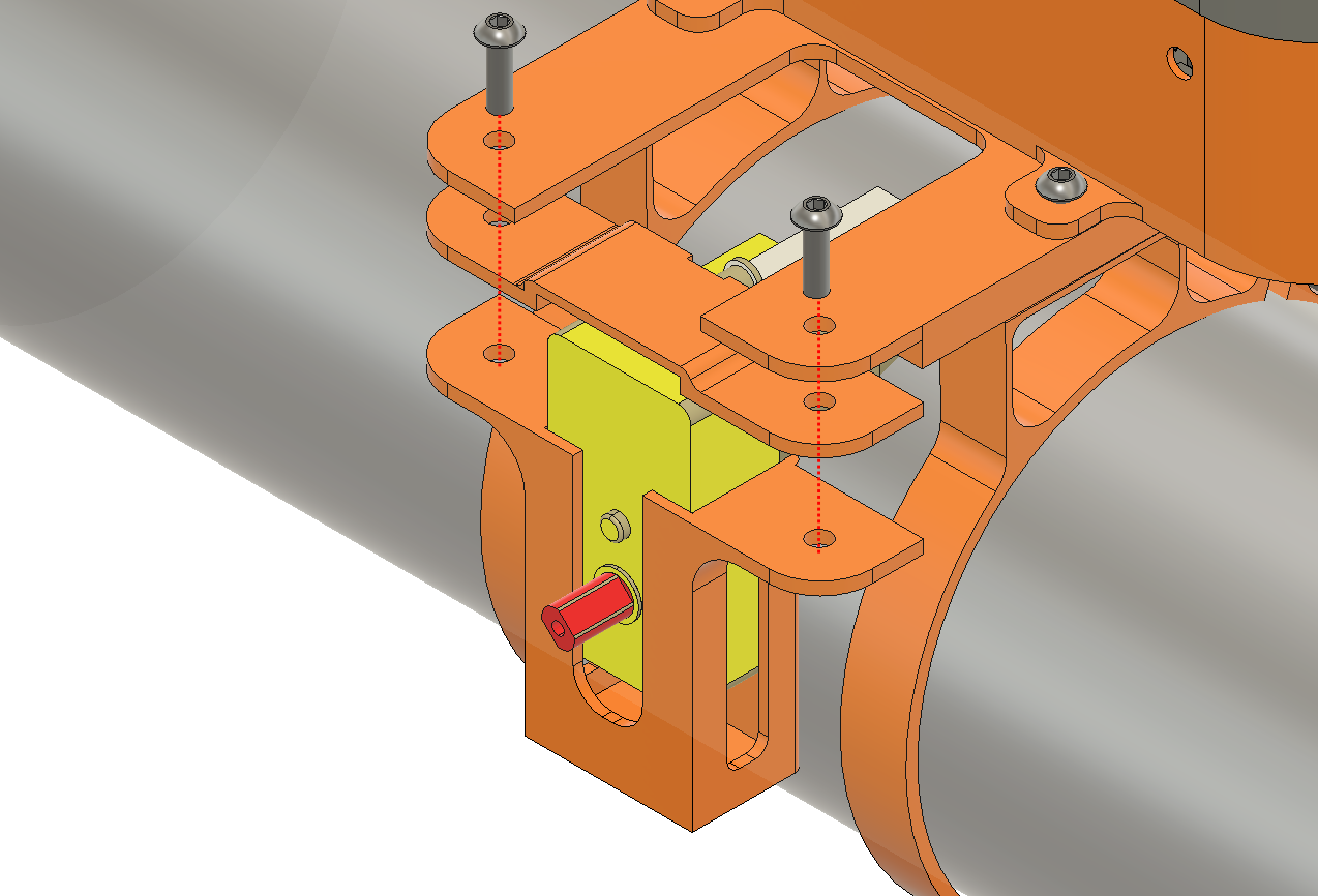
Insert the two rings into the bottle and partially tighten it with an M3 X 10mm screw, because we need to be able to move it later.
6.10
Screw in the main body, frame and the right using M3 x 15mm bolt and nut
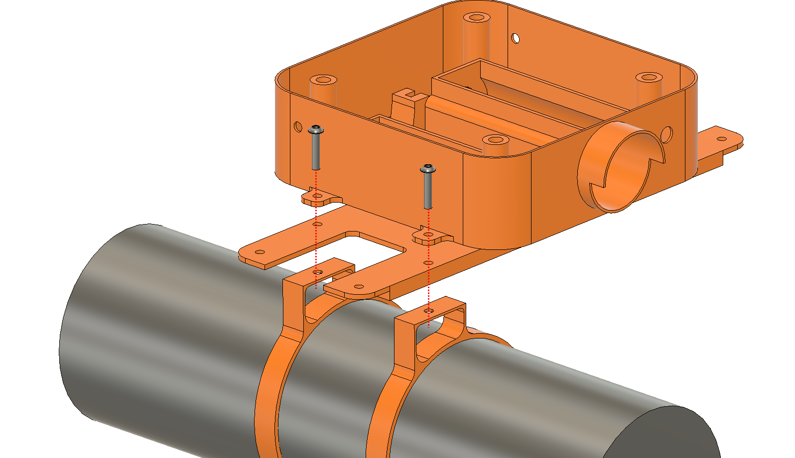
Do the same thing on the other side also
You can tighten the ring using an Allen key.
6.11
Inster the BO motor into the motor holder and fasten it with two M3X10mm Bolts and nuts
Do the same thing on the other side too.
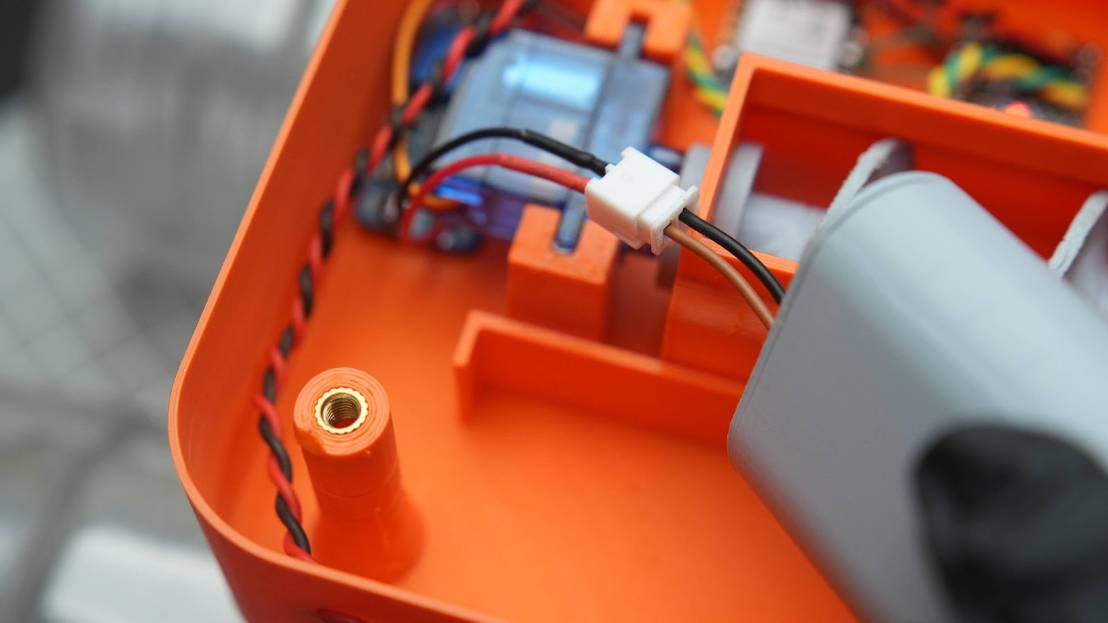
6.12
Twist two cables together, solder them into the motor, and run the wire through a side hole. Seal the hole with hot glue.
Do the same thing in the other side to
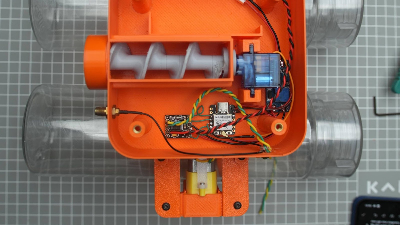
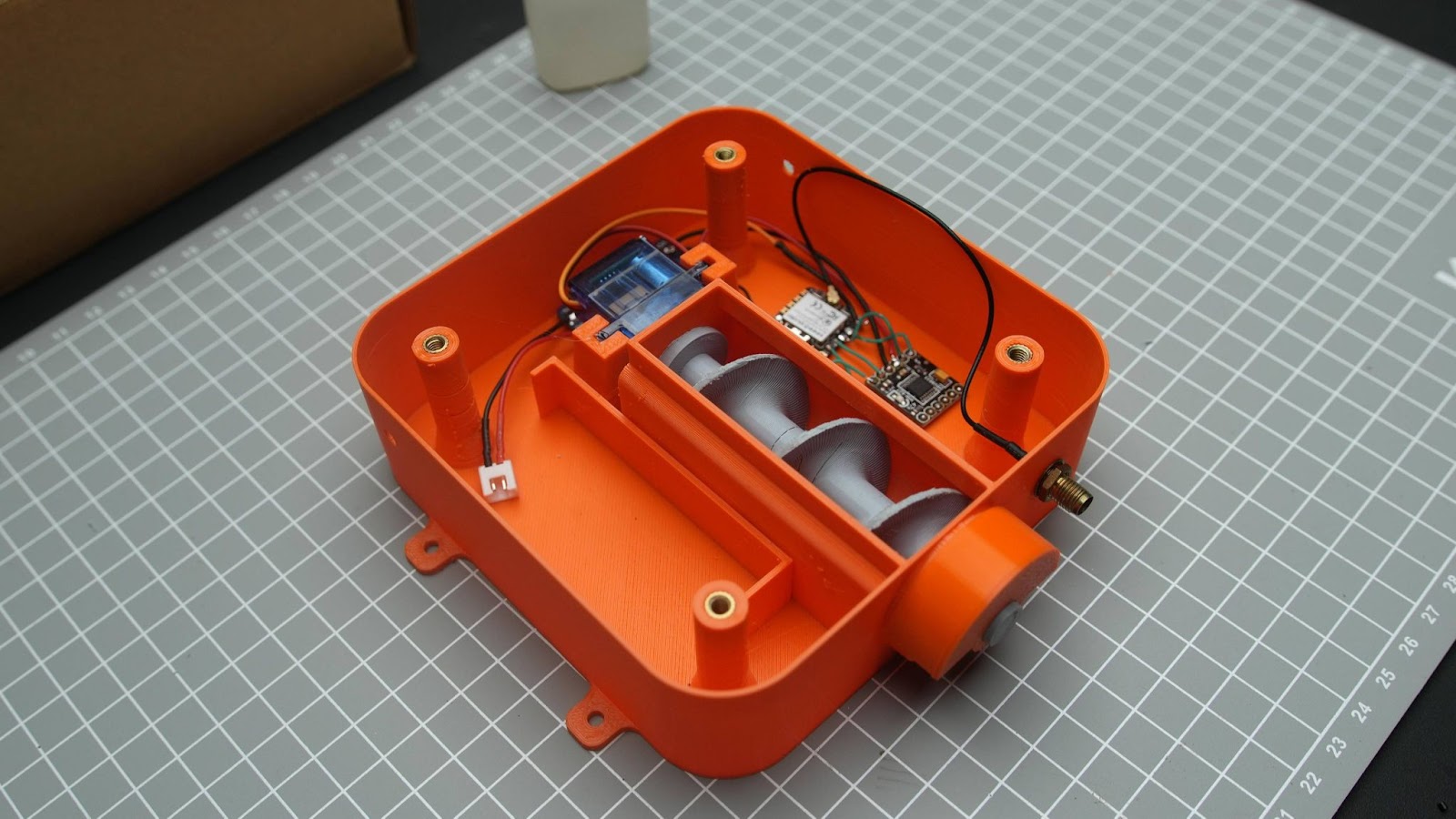
We just completed the main circuit assembly of the rover
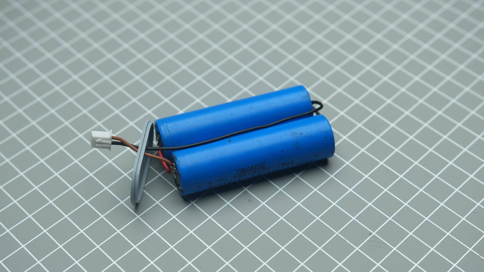
Step 7: Battery Pack
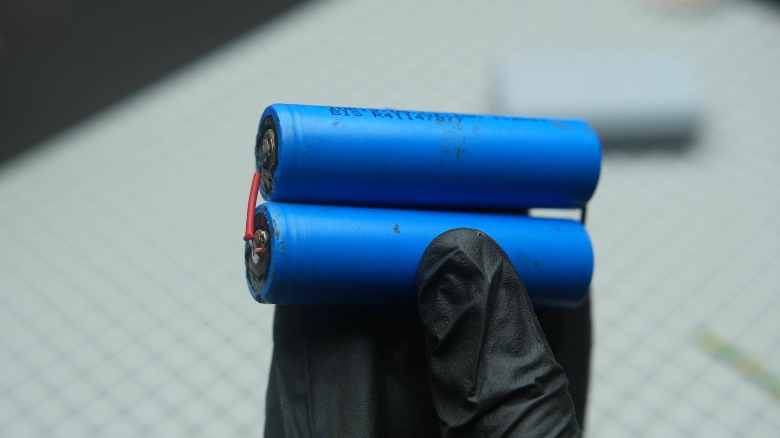
As you know we just completed the wiring of the rover but now we need to power source. for that, we are going to build a battery pack. It is a 1S 2p pack
7.1
Solder two battery is in parallel with wires
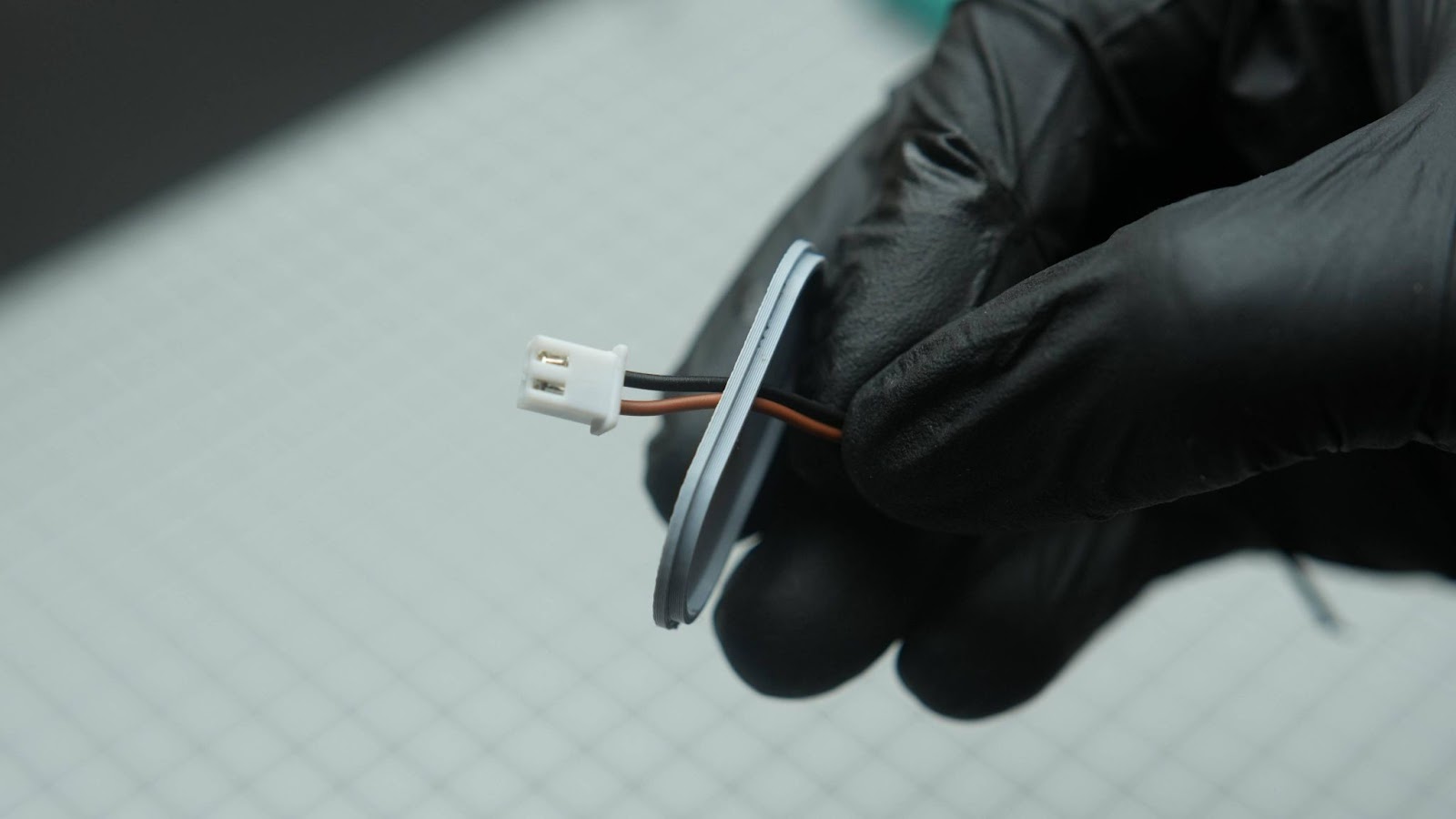
7.2
Run a male JST connector to the battery cap
7.3
Cut and Solder these JST wires into the battery back +ve and -ve
7.4
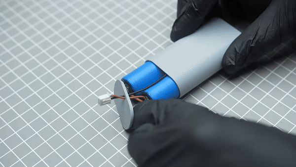
Insert the battery pack into the battery holder close the cap and glue the battery cap
You can recharge this battery pack using any 1S BMS just solder a JST connector to it
Also, you can connect the battery pack to the rover using this JST connector
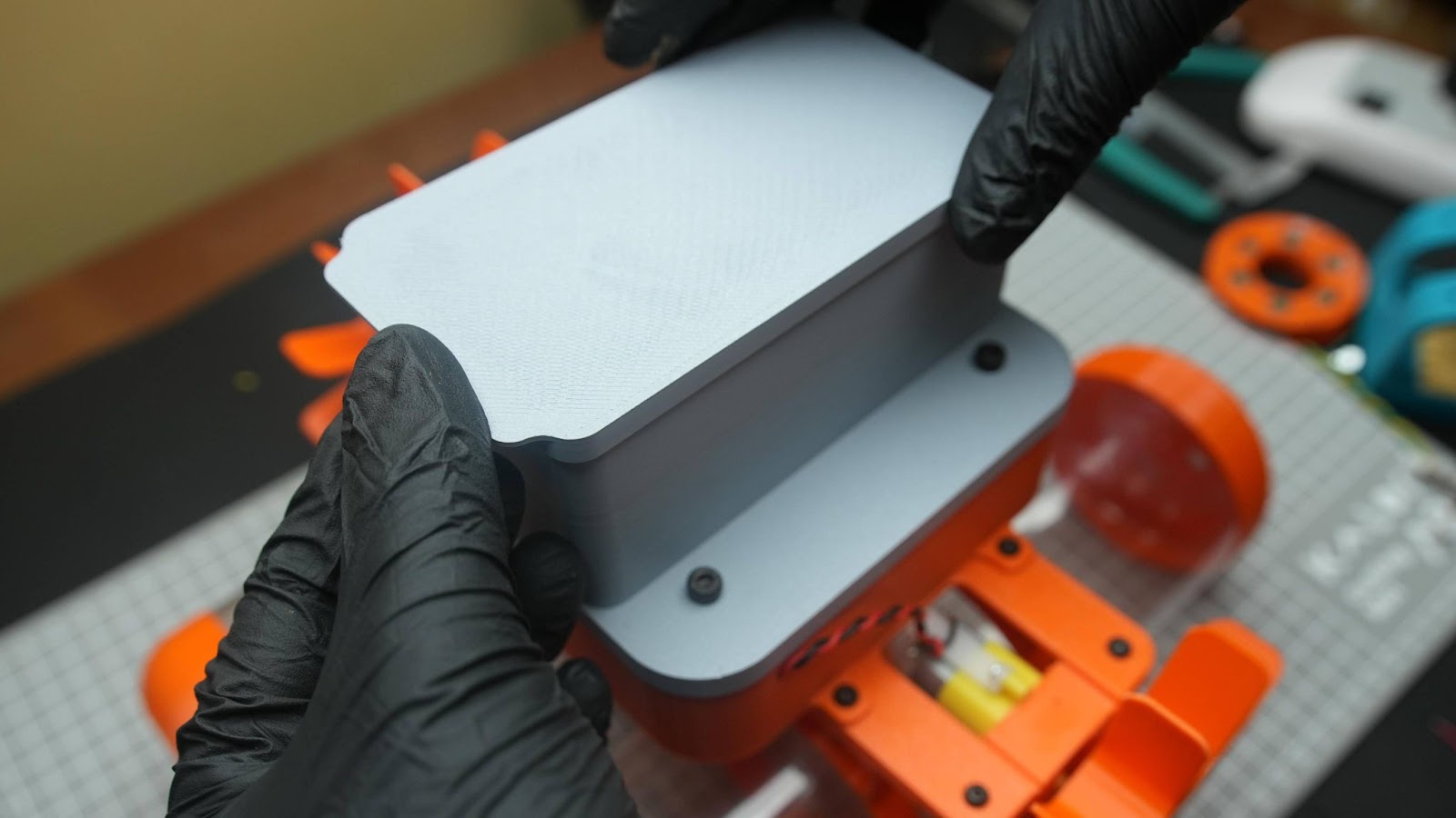
Step 8: Final Rover Assembly
8.1
Install the wheels into to motor shaft. I used the screw that ships with the BO motor
8.2
Install the top cap with the M4 bolts, you can remove it to access the battery
8.3
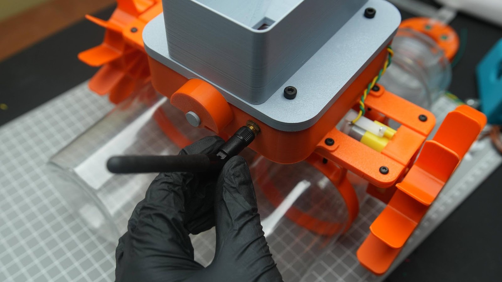
Connect the receiver antenna
8.4
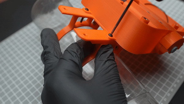
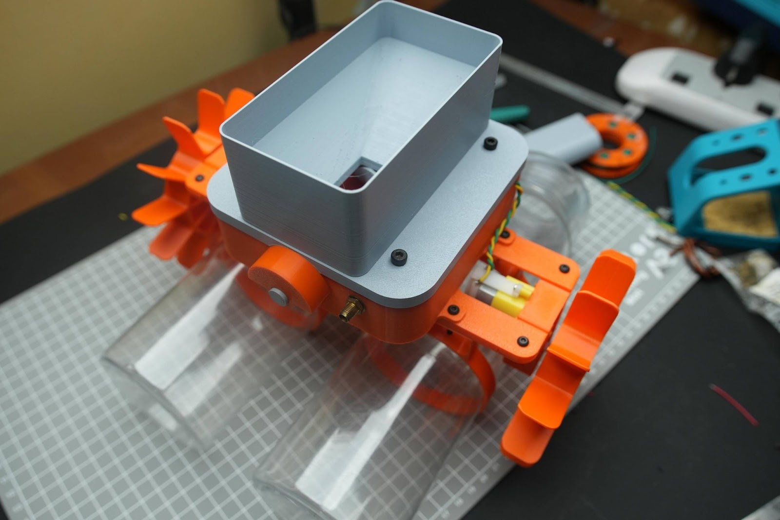
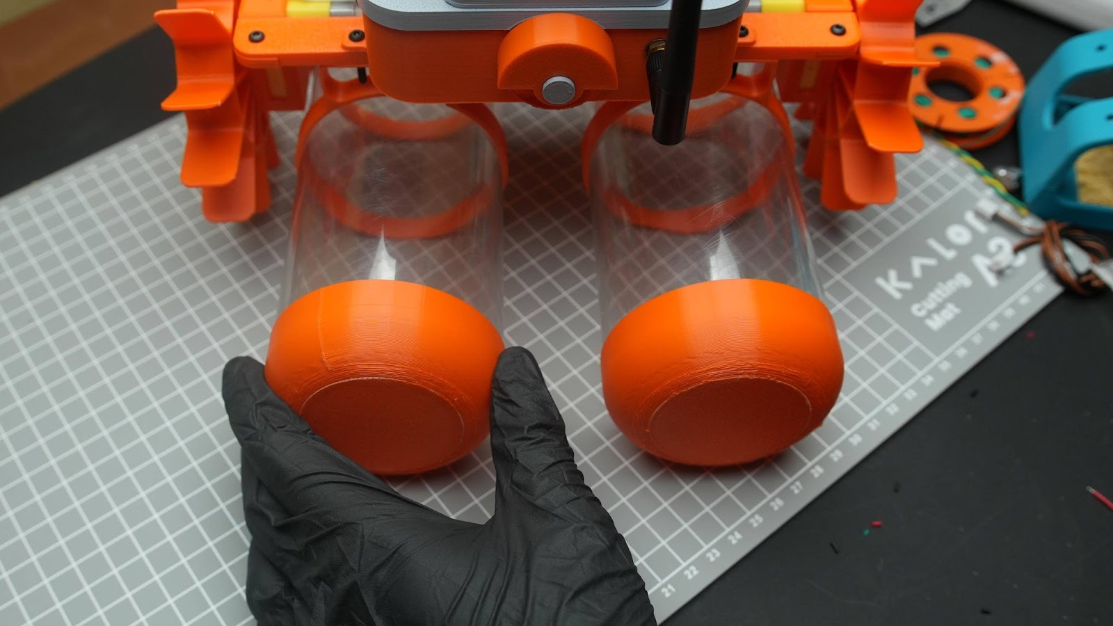
Install the 3d printed cups into bottles
8.5
You can use the payload cap to close the payload holder after filling it
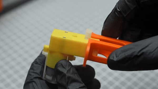
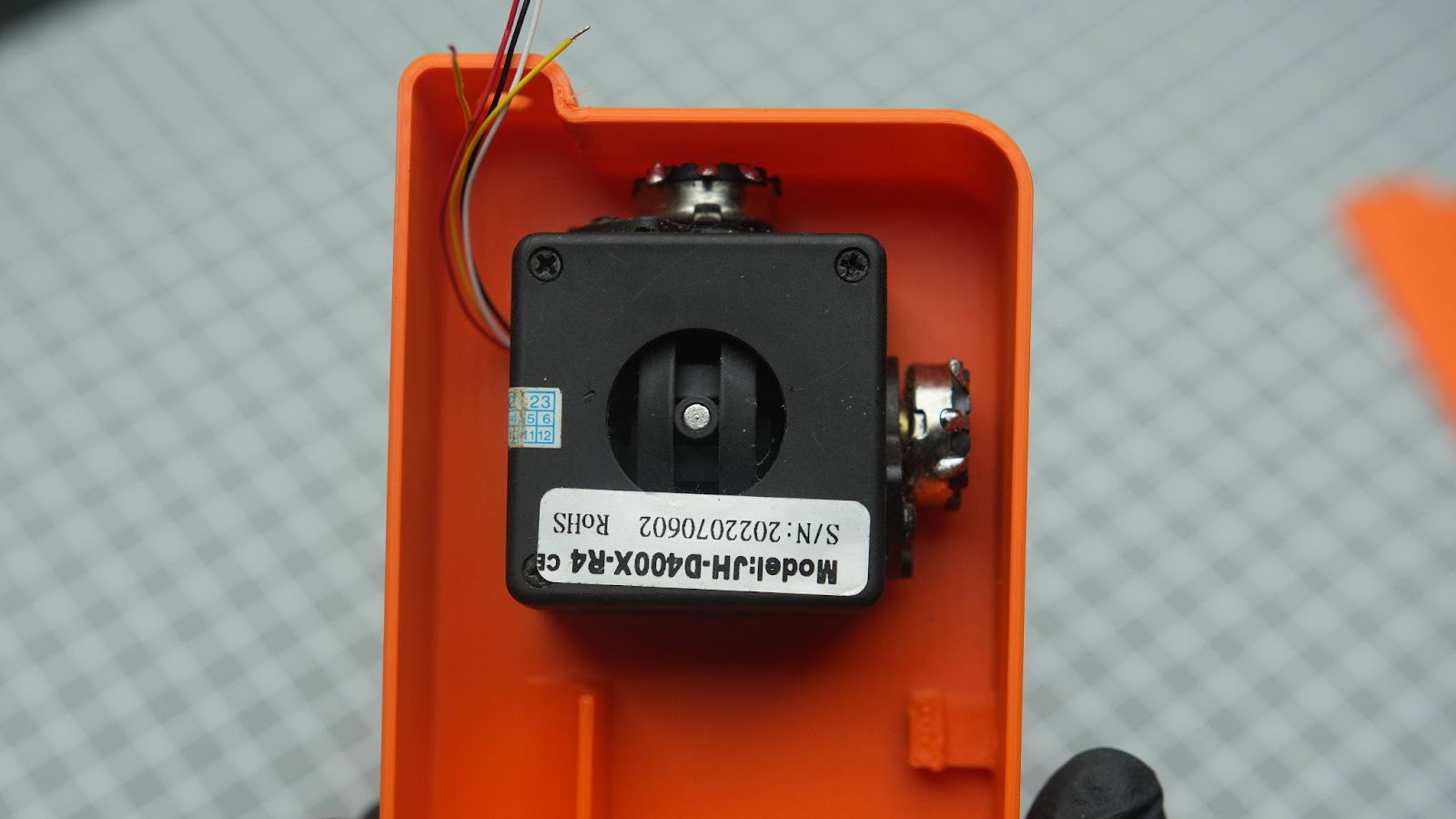
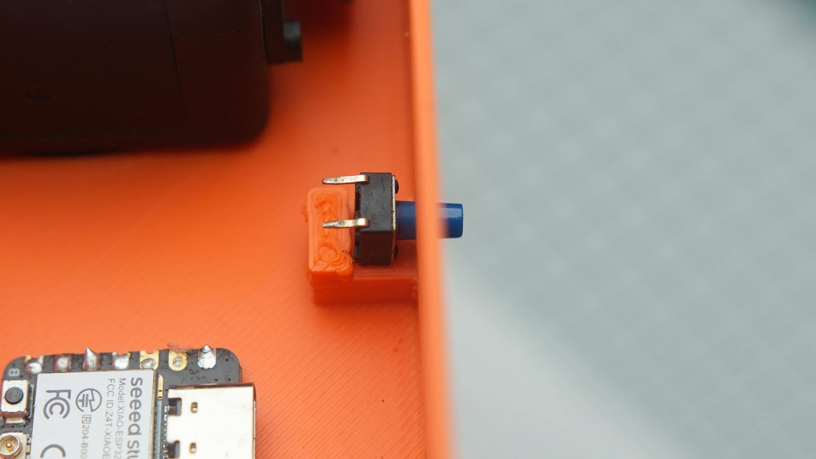
Step 9: Transmitter Assembly
9.1
Install the joystick into the transmitter's main body
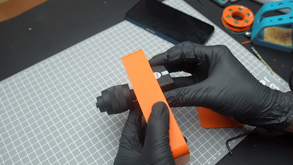
Make sure that the joystick orientation is similar to this image
9.1
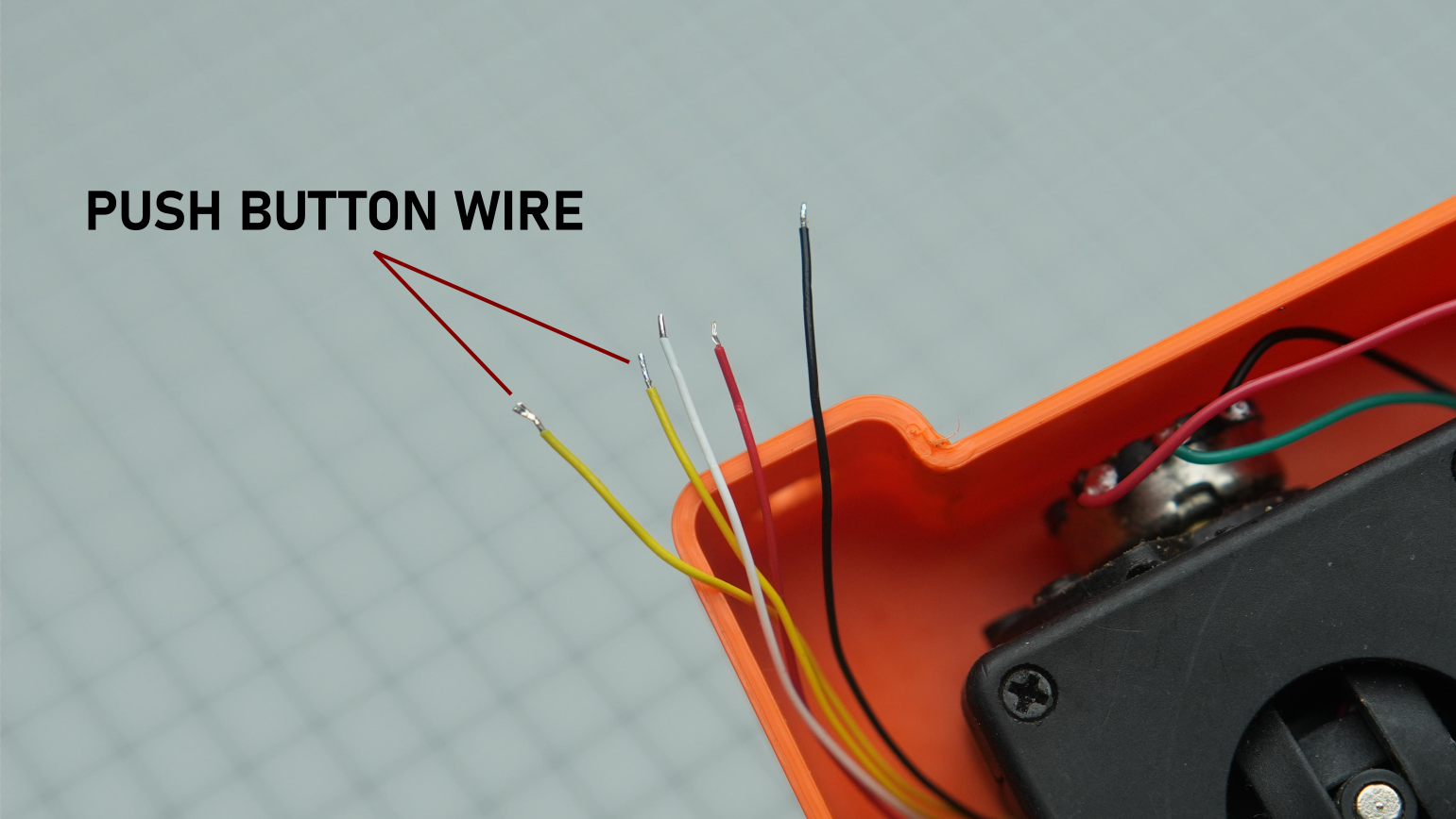
Cut 2 terminals of the push button place it into the3d printed slote and glue it
9.2
Solder 2 wires to the 18650 batteries
9.3
Glue the battery in the slot and complete the wiring according to the wiring diagram . the BMS module and XIAO is installed using glue
9.4
Connect the TX antenna in Xiao
Install the antenna port on the top side hole
9.5
Close the TX enclosure using the back cap. secure the back cap with some glue
We just completed the assembly of the TX
Step 10: Test
We have finished the build so now it's time to test it. You can load any pellet-sized food or medicine into the payload holder and close it with the top cap. During my initial test, I found that when I placed it in water, it was not balanced. So, you will need to loosen the floater clamp and adjust both of the water ballasts to achieve good overall balance
ESP32-Based 3D Printed Fish Feeder RC Board with ESP-Now Controller
*PCBWay community is a sharing platform. We are not responsible for any design issues and parameter issues (board thickness, surface finish, etc.) you choose.


- Comments(0)
- Likes(1)
 More by gokul kb
-
 ESP32-Based 3D Printed Fish Feeder RC Board with ESP-Now Controller
The original plan for this project was to create a fun RC Paddle Boat. However, during the project, ...
ESP32-Based 3D Printed Fish Feeder RC Board with ESP-Now Controller
The original plan for this project was to create a fun RC Paddle Boat. However, during the project, ...
-
 3D Printed Screw-propelled Robot With Video Feed
A screw-propelled vehicle is a type of land or amphibious vehicle that uses one or more auger-like c...
3D Printed Screw-propelled Robot With Video Feed
A screw-propelled vehicle is a type of land or amphibious vehicle that uses one or more auger-like c...
-
-
-
-
Tester for Touch Screen Digitizer without using microcontroller
334 2 2 -
Audio reactive glow LED wristband/bracelet with NFC / RFID-Tags
317 0 1 -
-
-


