


|
KiCad 9.0 |
|

|
InfluxDBInfluxdata
|
|

|
Ubuntu 22.04 LTSubuntu
|
|

|
RustRust Community
|
DC Power Unit for Breadboard
The Challenge
When experimenting with electronics, how do you power your breadboard? Most people use batteries, power adapters, or regulated power supplies, but each comes with significant drawbacks. Batteries are disposable and costly over time. Power adapters provide fixed voltages without adjustment capability. Regulated power supplies are bulky and impractical for portable work.
I wanted to create a more convenient breadboard power solution that could be easily used anywhere. Today, USB has evolved to support USB Power Delivery (PD) specification, enabling power delivery of up to 100W. Furthermore, USB-PD chargers supporting Extended Power Range (EPR) can provide voltages up to 48V/240W. USB-PD chargers are extremely compact, affordable, and widely available. I thought it would be simple and convenient to create a breadboard power supply using these USB-PD chargers.
The Vision
The DC Power Unit for Breadboard was conceived from a vision to create a compact, intelligent power distribution system that could:
- Bridge the gap between USB-PD sources and breadboard development needs
- Provide precise voltage control from 0V to 30V*1 with 10mV resolution
- Deliver high current capabilities up to 5A when supported by the source
- Offer real-time monitoring and data logging capabilities
- Maintain safety through comprehensive protection systems
- Enable remote monitoring and control through modern IoT connectivity
*1 Requires a 30V EPR-compatible USB-PD charger.
How It Works
Hardware Foundation
ESP32-S3-WROOM-1-N16R8: The intelligent heart of the system, providing:
- WiFi connectivity for remote monitoring and control
- Powerful processing capabilities for real-time PID control
- Rich peripheral support for sensors and displays
- Low power consumption for efficient operation
AP33772S USB-PD Controller: The power negotiation specialist that:
- Communicates with USB-PD sources using the PD protocol
- Supports both Standard Power Range (SPR) and Extended Power Range (EPR)
- Enumerates available Power Data Objects (PDOs) from connected sources
- Provides comprehensive protection features (UVP, OVP, OCP)
- Enables precise voltage and current requests
INA228 Current Sensor: The precision measurement engine offering:
- High-resolution current and voltage monitoring with 195µV resolution
- Shunt-based current measurement for accuracy
- Temperature compensation for drift correction
- Real-time power calculation capabilities
SSD1331 Color OLED: The user interface providing:
- Real-time display of voltage, current, power, and temperature
- WiFi connection status and battery level indicators
- Error messages and system status
- Intuitive visual feedback for user interactions
MOSFET Power Control: Efficiently manages power delivery:
Touch Interface Innovation
The capacitive touch interface provides intuitive control:
- Up/Down Touch: Voltage adjustment in 100mV steps (1V steps on long press)
- Left/Right Touch: Fine voltage adjustment in 10mV steps
- Center Touch: Output enable/disable (long press) and error message clearing (short press)
- Calibration: Up+Down combination for automatic offset calibration
Dual Output Flexibility
The system supports two output configurations:
- Single Positive Output: Standard positive voltage output with ground reference
- Dual Positive/Negative Output: Split voltage configuration providing ±V/2 from a single setting
Note: If you use 21V or higher voltage, input voltage is 28v or higher, and differential voltage is over 3V and output current is over 3A, the MOSFET device is in the high consumption state and the unit temperature may rise over 80 degrees Celsius. Please be careful about the temperature. You can set the maximum temperature in the configuration file. The default value is 80 degrees Celsius. If the temperature exceeds the limit, the output will be disabled automatically. I recommend using less than 0.7A current at 21V or higher voltage. Otherwise, if you set the output voltage to 27V or higher, the temperature rise is not a problem.
Note: This unit uses a micro controller and a USB PD controller. These controllers need the power to operate. Therefore, if you use a over current, the power source may be shut down by the over current protection of the PD charger. In this case, This unit cannot operate and will be turned off. Please use the current within the specification of your PD charger.
The Software Architecture
The software components is developed in Rust using the ESP-IDF framework, leveraging its strengths for embedded systems:
main.rs - Core system orchestration and sensor interfacing usbpd.rs - AP33772S driver wrapper with ESP32 integration displayctl.rs - OLED display management and user interface currentlogs.rs - Data logging with intelligent buffer management touchpad.rs - Capacitive touch sensor interface pidcont.rs - PID controller for voltage regulation wifi.rs - WiFi connectivity and network management transfer.rs - InfluxDB data transmission with retry logic syslogger.rs - System logging and diagnostics
Advanced Control Systems
PID Controller: Maintains precise output voltage through:
- Proportional control for immediate response
- Integral control for steady-state accuracy
- Derivative control for stability and overshoot prevention
- Automatic reset on voltage overshoot detection (>110% of setpoint)
PDO-Aware Limiting: The system intelligently:
- Enumerates available PDOs from connected sources
- Applies the most restrictive limits between configuration and PDO capabilities
- Prevents exceeding source capabilities while maximizing available power
NVS Memory Management: Persistent storage capabilities:
- Saves last used voltage setting for convenience
- Stores calibration data for accuracy across power cycles
- Maintains configuration parameters in non-volatile storage
The Data Pipeline
Local Intelligence
The system continuously:
- Samples voltage and current at 10ms intervals for responsive control
- Calculates power consumption in real-time
- Monitors temperature for thermal protection
- Manages buffer storage during network outages
- Network Connectivity
When WiFi is available:
- Transmits measurement data to InfluxDB time-series database
- Provides remote monitoring capabilities through web dashboards
- Enables historical analysis and trend monitoring
- Supports multiple device monitoring for larger installations
- Intelligent Buffer Management
During network outages:
- Automatically stores measurements in local memory
- Provides visual feedback of buffer utilization
- Resumes logging automatically when connectivity returns
- Prevents data loss during intermittent connectivity
Safety and Protection Systems
Multi-Layer Protection
- Hardware Protection: AP33772S built-in UVP, OVP, and OCP
- Software Monitoring: Continuous temperature and current monitoring
- User-Configurable Limits: Maximum current, power, and temperature settings
- PDO Compliance: Automatic limiting to source capabilities
- Emergency Shutdown: Immediate output disable on fault conditions
Temperature Management
- Real-Time Monitoring: Continuous temperature sensing with 0.05°C resolution
- Configurable Limits: User-settable maximum temperature threshold (default 80°C)
- Automatic Protection: Output disable when temperature limits are exceeded
- Visual Feedback: Temperature display and warning messages
Schematic Diagram
Schematic diagrams are created using Kicad. "Sheet1" to "Sheet5" are the schematic diagrams of the main board and the adaptor boards.
Sheet1: USB PD Controller and Power Regulator Circuit
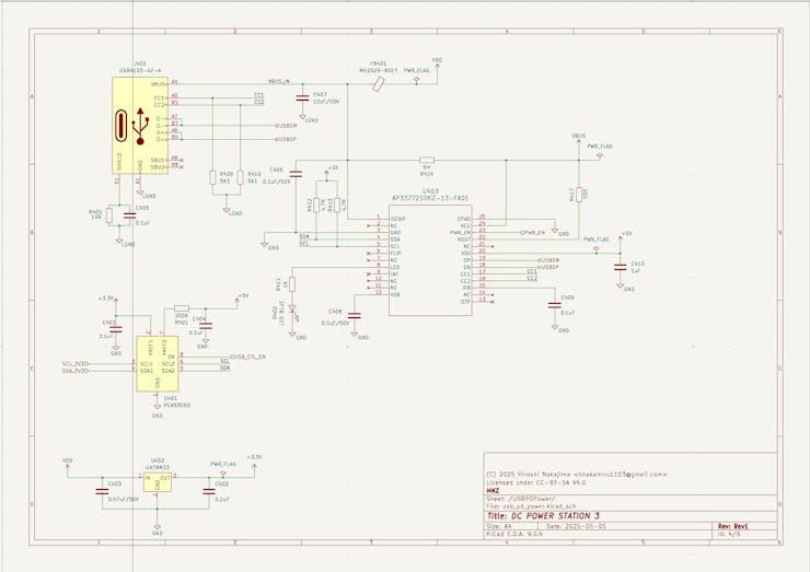
AP33772S USB-PD Controller is used for the USB PD communication and power negotiation. This controller is connected to the ESP32 microcontroller via I2C interface with Voltage level shifter.
Sheet2: ESP32 Microcontroller and SSD1331 OLED Display Circuit
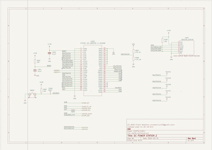
SSD1331 Color OLED display is connected to the ESP32 microcontroller via SPI interface. GPIO(IO1, IO2, IO3, IO4, IO5) are used for the touch interface. Just connect the IO1 to IO5 to the touch pads.
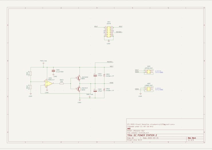
Sheet3: Power Path Management, Current Sensor and Temperature Sensor Circuit
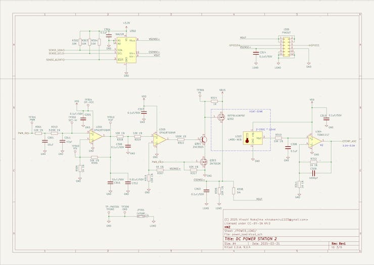
INA228 current sensor is used for the current and voltage measurement. The shunt resistor (5mΩ) is connected to the INA228. ESP32 Controller has the PWM output for the MOSFET gate driver. The PWM signal is connected to the LPF(Low Pass Filter) and OPAmp(Operational Amplifier) circuit for the voltage control. The OpAmp is used for the voltage follower to drive the MOSFET gate. The first OpAmp is gain =11 and the second OpAmp is gain =1.1. The output voltage is controlled by the PWM duty cycle. The temperature sensor (LM35) is used for the temperature measurement. The output of the temperature sensor is connected to the OpAmp (gain=2) and then connected to the ADC of the ESP32. The output voltage is feedback to the OpAmp and INA228 for the voltage and current measurement.
Sheet4: Adaptor Circuit for Single Voltage Output Configuration
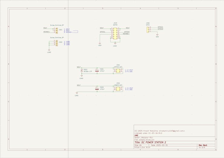
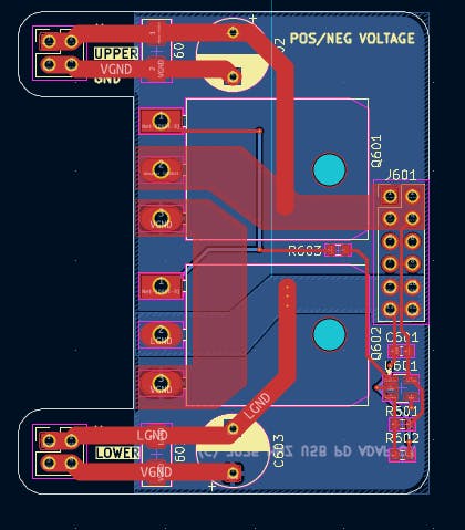
Sheet5: Adaptor Circuit for Dual Voltage (Positive and Negative) Output Configuration
The output voltage is divided into two by the voltage divider circuit. The output voltage is ±V/2.
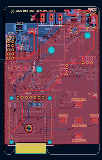
PCBs Design
I designed a custom PCBs by Kicad.
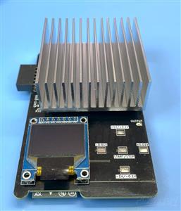
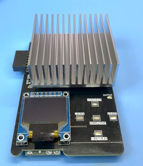
The Main PCB has the ESP32-S3-WROOM-1-N16R8 module, AP33772S USB-PD controller, INA228 current sensor, SSD1331 color OLED display, MOSFET power control circuit, and other components. The main PCB has one connector for the adaptor board and the USB-C connector for the USB-PD input.
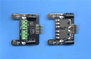
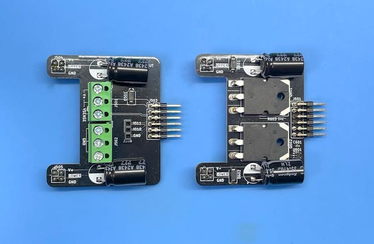
The Adaptor PCB has the output connector and the power path management circuit. There are two types of adaptor boards. One is for the single voltage output configuration, and the other is for the dual voltage (positive and negative) output configuration. You can choose the adaptor board according to your application. The main PCB and the adaptor PCB are connected by a 12-pin connector.
Adaptor PCB for Single Voltage Output Configuration
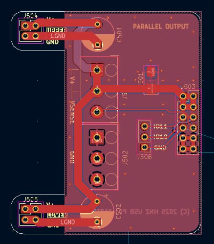
Adaptor PCB for Dual Voltage (Positive and Negative) Output Configuration
How to order the PCB
After it is designed, I ordered PCBWay (https://www.pcbway.com/) to manufacture my board. It is pretty easy to order the board. Click the "Add Gerber File" button, and you can upload the Gerber file. Then, you can choose solder mask color. I chose the Matte Black color I like this one. The board is manufactured in only few days. I am very satisfied with the board. I think the PCBWay's board price is very reasonable to with the service.
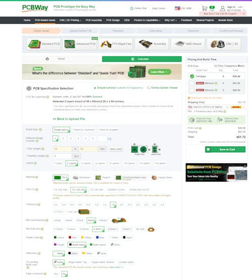
PCBWay has a special discount campaign for all orders. There are two types of campaigns. One is for Purple Solder Mask: the starting price of purple is $38.43, but in the October, it's $5. The other is for TPU in 3D printing, this material starts from $12.45, but, it will be start from $7.96 forever. The heavier the weight, the bigger the discount, which can be up to 40% off.
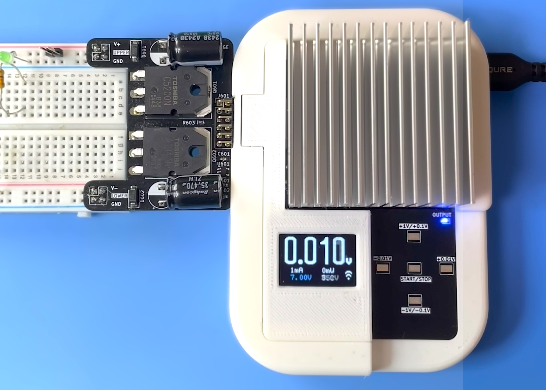
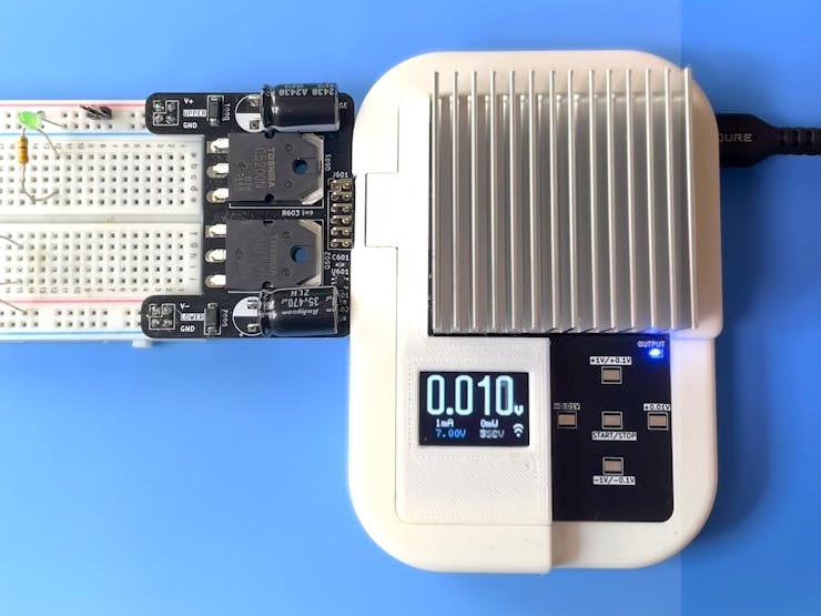
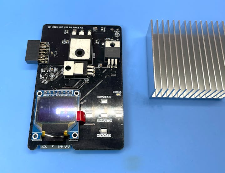
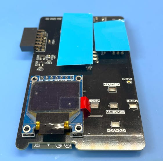
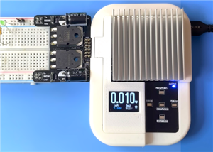
After assembly, the board looks like this. Heat sink is attached to the back of the MOSFETs using thermal adhesive tape.
How to build from code and Install to the unit.
Using Ubuntu 22.04.3 LTS and ESP-IDF V5.4.2
Prerequisites
Ensure that your system meets the following requirements before proceeding with the installation:
- Operating System: Linux-based distribution
- Required Packages: git, python3, python3-pip, gcc, build-essential, curl, pkg-config, libudev-dev, libtinfo5, clang, libclang-dev, llvm-dev, udev, libssl-dev, python3.10-venv
Installation Steps
1. System Update and Package Installation
Update your system and install the necessary packages using:
sudo apt update && sudo apt -y install git python3 python3-pip gcc build-essential curl pkg-config libudev-dev libtinfo5 clang libclang-dev llvm-dev udev libssl-dev python3.10-venv
2. Rust Installation
Install Rust programming language and Cargo package manager:
curl --proto '=https' --tlsv1.2 -sSf https://sh.rustup.rs | sh
After installation, activate Rust by sourcing the environment:
. "$HOME/.cargo/env"
3. Additional Tools Installation
Install the following Rust tools:
- ldproxy
- espup
- cargo-espflash
Use the following commands:
cargo install ldproxy cargo install espup cargo install cargo-espflash
At this time (2025-07-25), espup cannot be compiled. If you get an error, please use the following command to install the toolchain.
cargo install cargo-binstall cargo binstall espup
4. ESP Environment Setup
Run the following command to install and update the Espressif Rust ecosystem:
espup install espup update
Set up environment variables:
. ./export-esp.sh
5. Udev Rules Configuration
Configure udev rules for device permissions:
sudo sh -c 'echo "SUBSYSTEMS==\"usb\", ATTRS{idVendor}==\"303a\", ATTRS{idProduct}==\"1001\", MODE=\"0666\"" > /etc/udev/rules.d/99-esp32.rules' sudo udevadm control --reload-rules sudo udevadm trigger
6. Clone Repository
Clone the DC Power Unit repository:
git clone https://github.com/hnz1102/dcpower.git cd dcpower/code
7. Setting WiFi SSID, Password, etc.
Change the following configuration file: `cfg.toml`
You have to set the following parameters: WiFi SSID, Password, InfluxDB Server IP Address, InfluxDB API Key, and InfluxDB API with your ORG.
You can get the API Key from the InfluxDB Web Console. Please see the 'How to Install the InfluxDB and Configure the Dashboard' section No.3.
[dcpowerunit] wifi_ssid = "<Your AP SSID>" # Set your AP SSID wifi_psk = "<Your AP Password>" # Set your AP Password influxdb_server = "<InfluxDB Server IP Address:Port>" # Set your InfluxDB Server IP Address and Port ex. 192.168.1.100:8086 pid_kp = "0.0000005" pid_ki = "0.00002" pid_kd = "0.1" pwm_offset = "0" pd_config_offset = "1.5" shunt_resistance = "0.005" shunt_temp_coefficient = "50" max_current_limit = "5.2" max_power_limit = "100.0" max_temperature_limit = "75" # Set the maximum temperature limit in degrees Celsius. Default is 75 degrees. influxdb_api_key = "<InfluxDB API KEY>" # Set your InfluxDB API Key influxdb_api = "/api/v2/write?org=<ORG>&bucket=LOGGER&precision=ns" # Set your InfluxDB API with your ORG and BUCKET influxdb_tag = "dcpowerunit" # Tag for InfluxDB measurements influxdb_measurement = "dcpowerunit" # Measurement name for InfluxDB syslog_server = "<Syslog Server IP Address:Port>" # Set your Syslog Server IP Address and Port ex. 192.168.2.140:514 syslog_enable = "false" # Set to "true" to enable syslog
8. Build and Flash
Build the project:
cargo build --release
9. Flash the Firmware
Connect the DC Power Unit to your PC using a USB cable. Then, flash the firmware:
cargo espflash flash --release --monitor
If your device is not detected, power on the device and during the boot, press the `BOOT` button.
Then, run the flash command again.
10. Monitor the Output
After flashing the firmware, the console shows the booting messages and system initialization including:
WiFi connection status AP33772S USB-PD controller initialization Available PDO (Power Data Object) detection Touch interface activation OLED display initialization Chip type: esp32s3 (revision v0.2) Crystal frequency: 40 MHz Flash size: 16MB Features: WiFi, BLE, Embedded Flash MAC address: 80:65:99:b8:8e:90 App/part. size: 1,383,760/1,536,000 bytes, 90.09% [00:00:00] [========================================] 14/14 0x0 Verifying... OK! [00:00:00] [========================================] 1/1 0x8000 Skipped! (checksum matches) [00:00:15] [========================================] 864/864 0x10000 Verifying... OK! [2025-09-15T07:23:38Z INFO ] Flashing has completed! :
How to Install the influxDB and Configure the Dashboard
1. Download influxDB(https://docs.influxdata.com/influxdb/v2.7/install/?t=Linux) and Install.
$ wget https://dl.influxdata.com/influxdb/releases/influxdb2-2.7.0-amd64.deb $ sudo dpkg -i influxdb2-2.7.0-amd64.deb $ sudo service influxdb start
2. Configure the influxDB
Connect to the 'http://<influxDB installed PC Address>:8086'
Click `GET STARTED` and set `Username`, `Password`, `Initial Organization Name`, and `Initial Bucket Name`
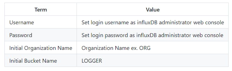
After set them, click `CONTINUE`.
3. Copy the operator API token.
You can see the operator API token on the browser. YOU WON'T BE ABLE TO SEE IT AGAIN!
If you want to get new API token, click `API Tokens` menu form `Sources` Icon, then click `GENERATE API TOKEN` and select `All access token`, click `Save`.
You can see a new API token and get it.
After copy the token, click `CONFIGURE LATER`.
4. Import the Dashboard Template.
Click the `Dashboard` icon, and select `Import Dashboard` from the `CREATE DASHBOARD` menu.
Drop the `influxdb/dc_power_station.json` file to `Drop a file here`, then click `IMPORT JSON AS DASHBOARD`.
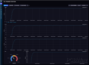
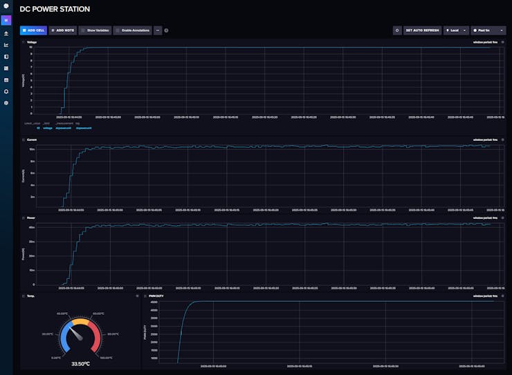
You can see the `DC POWER STATION` pannel on the Dashboards page.
Click this panel, and You can see the dashboard.

If you want to customize the dashboard design, click configure mark. You can change the graph design.
Conclusion
The DC Power Unit for Breadboard will give you a compact, intelligent, and flexible power solution for your electronics projects. USB-PD chargers are ubiquitous, affordable, and capable of delivering high power in a small form factor. This Unit can provide precise voltage control, real-time monitoring, and robust safety features, all accessible remotely via WiFi.
Finally, I would like to thank PCBWay for their support of the custom PCB board.
LICENSE
This source code is licensed under MIT. Other Hardware Schematic documents are licensed under CC-BY-SA V4.0.
DC Power Unit for Breadboard
Project images are for reference only. Actual production is based on the manufacturing files on the project page.
Please review the designer's notes (e.g., PCB thickness) and select the appropriate options.
PCBWay is not responsible
for issues caused by unsuitable parameter selections.
For more important ordering information, please refer to
Read More


Raspberry Pi 5 7 Inch Touch Screen IPS 1024x600 HD LCD HDMI-compatible Display for RPI 4B 3B+ OPI 5 AIDA64 PC Secondary Screen(Without Speaker)
BUY NOW


- Comments(0)
- Likes(4)
More by Hiroshi Nakajima
-
 Digitally Controlled Electric Load
About ThisAn Electronic Load is a device that simulates the behavior of an electronic component unde...
Digitally Controlled Electric Load
About ThisAn Electronic Load is a device that simulates the behavior of an electronic component unde...
-
 DC Power Unit for Breadboard
The ChallengeWhen experimenting with electronics, how do you power your breadboard? Most people use ...
DC Power Unit for Breadboard
The ChallengeWhen experimenting with electronics, how do you power your breadboard? Most people use ...
-
 Time Leap Cam - Time-Lapse Cam and Monitoring by OpenAI
About This CameraThis camera, named "TIME LEAP CAM," is designed for long-interval time-lapse photog...
Time Leap Cam - Time-Lapse Cam and Monitoring by OpenAI
About This CameraThis camera, named "TIME LEAP CAM," is designed for long-interval time-lapse photog...
-
 Share USB Memory with One-touch Switching Between Two Device
When the network is not available, data is transferred by copying data to and from a USB memory stic...
Share USB Memory with One-touch Switching Between Two Device
When the network is not available, data is transferred by copying data to and from a USB memory stic...
-
 High-resolution Voltage-Current Digital Logger
Voltage-Current Logger - High-resolution digital power monitor and loggerI wanted a tool to measure ...
High-resolution Voltage-Current Digital Logger
Voltage-Current Logger - High-resolution digital power monitor and loggerI wanted a tool to measure ...
-
 SDCDMUX : SD Card and eMMC Device Multiplexsor with Infrared Remote Control
The SDCDMUX provides a convenient and quick change of a SW image of a device that has an SD Card int...
SDCDMUX : SD Card and eMMC Device Multiplexsor with Infrared Remote Control
The SDCDMUX provides a convenient and quick change of a SW image of a device that has an SD Card int...
-
Programmable Mist Maker - XIAO / QT PY Extension
1074 2 1 -
RadioHAT - Raspberry Pi radio development platform
891 0 2 -
-
-
-
-
ARPS-2 – Arduino-Compatible Robot Project Shield for Arduino UNO
3334 0 6 -
A Compact Charging Breakout Board For Waveshare ESP32-C3
3945 3 8 -
AI-driven LoRa & LLM-enabled Kiosk & Food Delivery System
4335 2 2


