


|
KiCad 8.0KiCad
|
|

|
Thonny IDE |
BEAPER Pico 0.1: A (Prototype) Beginner Electronics and Programming Educational Robot for Raspberry Pi Pico
Background
I have been teaching high school electronics and computer technology courses for over thirty years, and in that time I've created a number of different beginner circuits to help my students learn about electronics and microcontroller programming. I try to design these beginner circuits using a modular approach which allows them to be assembled and used in different configurations.
Modular circuits don't need to have all of their components installed for beginners to start using them to learn programming fundamentals. Instead, learners can start programming after assembling a quicker-to-build, and lower cost subset of the full circuit. Learners can expand their circuit's feature set and capabilities by simply installing additional groups of components later, which lets their circuits grow with them as they improve their software skills and interfacing abilities.
Modular designs are especially great for classrooms and makerspaces, since the circuits can be assembled at a lower cost using only the parts required to achieve the learning goals. At the same time, their expandability allows the circuits to be customized for specific projects, or to provide higher level opportunities for more advanced learners. The big plus for instructors is that all of the circuits, for learners at all levels, can make use of the same common components and lesson outlines!
Meet BEAPER Pico
This past August I presented my BEAPER Nano project at a conference for computer studies teachers. It's a modular beginner microcontroller board made for the newer Arduino Nano ESP32, and each of the teachers attending my session made theirs into a BEAPER Bot robot. The session was well received and some of the teachers asked about the possibility of creating a similar robot for the Raspberry Pi Pico family of microcontroller boards, since these circuits are available at a lower cost than the Arduino Nano ESP32.
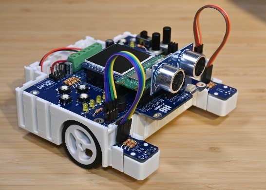
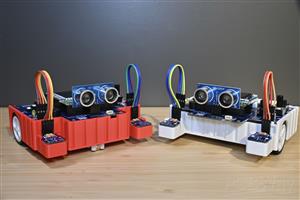
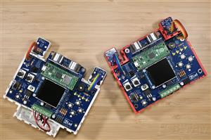
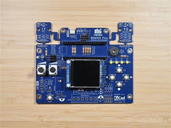
The Raspberry Pi Pico form factor is slightly larger than the Arduino Nano ESP2, but I thought it should be possible for me to squeeze a Raspberry Pi Pico into the same physical circuit form factor in order to fit the already created BEAPER Bot robot chassis I had originally designed around the dimensions of the BEAPER Nano. The result is this prototype BEAPER Pico, the Beginner Electronics And Programming Educational Robot for Raspberry Pi Pico. The Raspberry Pi Pico is a tighter fit on the PCB, and its larger size results in too little free space around the USB cable, so I'm not totally happy with this design yet. But, these are challenges I can look forward to resolving in the next revision!
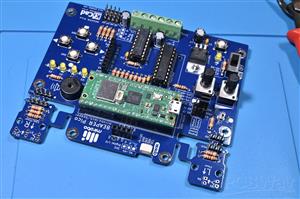
Just like BEAPER Nano, I wanted BEAPER Pico to be simple enough to be able to be used as a beginner learning circuit for microcontroller programming, while simultaneously being versatile enough to support the more advanced capabilities of the the Raspberry Pi Pico. To make initial circuit board assembly easy for novices, as well as to simplify the addition of more components as learners progressed, the printed circuit board (PCB) has been created as a through-hole design. And, BEAPER Pico PCB is designed to have the exact same dimensions as BEAPER Nano, so it will be just as easy for beginners to make it into a robot using the 3D-printable BEAPER Bot chassis design and add-on parts.
BEAPER Pico Configurations
BEAPER Pico can be built in multiple ways, but there are three common configurations that I think make the most sense: an education starter configuration containing only the components needed for beginners to start learning introductory microcontroller programming, a robot starter configuration enabling BEAPER Pico to run from batteries, drive motors, and be made into simple robots, and an analog I/O configuration providing a variety of analog input devices for making robot floor and line sensors, as well as light and position sensors for learning more advanced analog input and processing techniques. BEAPER Pico's components have been grouped into these three configurations, below, along with expansion components that overlap between configurations, or are more specialized and provide even greater learning opportunities. Let's get to know the components that make up each configuration.
Education starter configuration components
- four pushbuttons
- four LEDs
- piezo speaker
- header sockets for the Raspberry Pi Pico
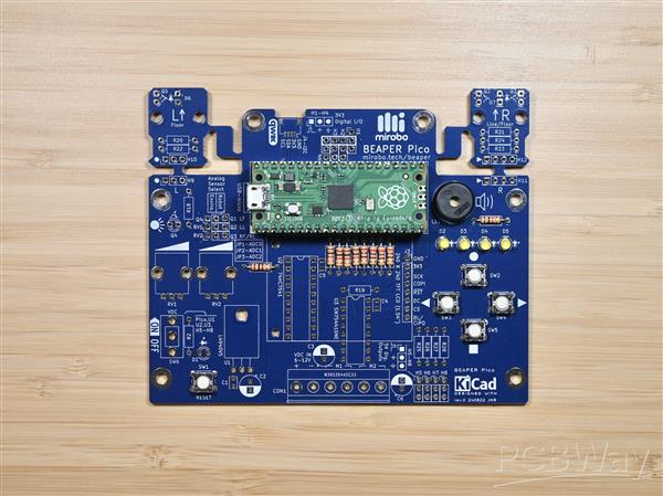
New learners can start exploring introductory microcontroller programming concepts using only the education starter components installed in their BEAPER Pico. Building these simple circuits directly onto a PCB allows beginners to focus on learning programming without having to build and debug potentially unreliable breadboard circuits in between. This can save lots of time and frustration for new learners, and can lower costs and reduce project storage space requirements in schools.
Robot starter configuration components
- screw terminal strip and power switch
- 5V low drop-out voltage regulator circuit
- 3.3V to 5V level shifter IC
- H-bridge motor driver IC
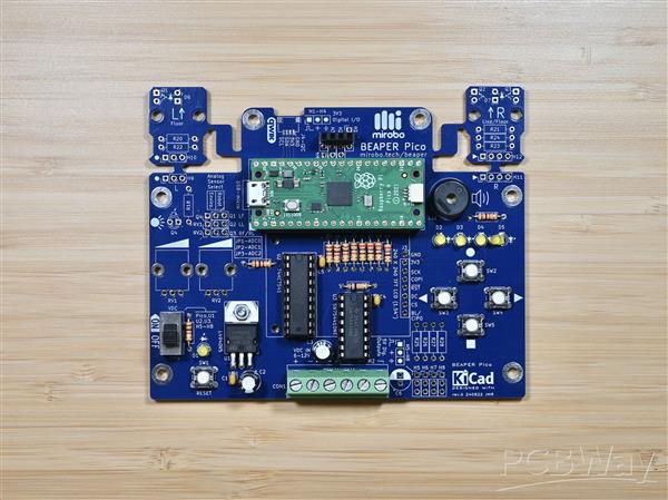
The robot starter configuration adds all of the electronic parts needed to drive two DC motors while powering BEAPER Pico using batteries. An ultrasonic SONAR distance sensor module can be installed into a header socket bridging headers H1-H4 (at the top middle of the PCB), and optical floor and line sensors can be built by installing LEDs and phototransistors into the break-away left and right optical sensor modules (top left, and top right, labelled with the large letters L and R).
Analog I/O configuration components
- ambient light sensor
- two rotary potentiometers
- two break-away optical floor and line sensor modules using LEDs and phototransistors
Analog components are great for learning more advanced input processing techniques, and can help new users simulate their robot floor sensors or other analog input devices. BEAPER Pico includes an ambient light sensor, which when combined with the temperature sensor and WiFi module built into the Raspberry Pi Pico W can be useful in making remote monitoring IoT devices. The on-board potentiometers can be used by learners to easily set program parameters or to control servos, and the optical phototransistors can be used to make robot line and floor sensors.
Expansion components
- four 3.3V digital I/O headers that can be bridged with a socket to hold an ultrasonic SONAR distance sensor module
- four 5V output-only headers (shared with the 3.3V digital headers) to drive servos or other 5V devices
- QWIIC connector to connect 3.3V I2C peripherals
- SPI breakout connector designed to mount a full colour, 1.54" graphical TFT LCD display panel
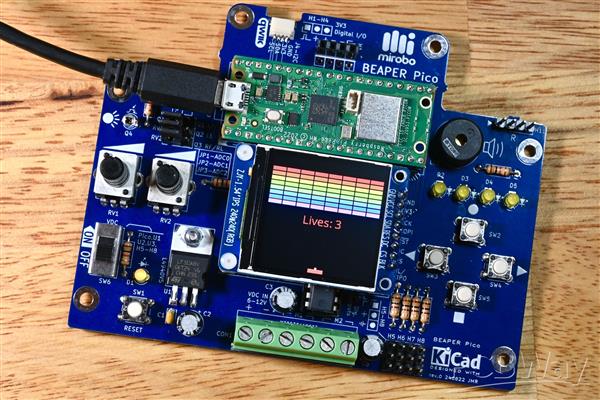
The expansion components enable all kinds of additional circuits and components to be added to BEAPER Pico, expanding its capabilities beyond many other simple beginner circuits. Adding a graphical LCD display can challenge more advanced learners to program user interfaces or even simple games, such as this block breaker game.
Beyond the on-board circuitry, the built-in wireless capabilities of the Raspberry Pi Pico W enable learners to create programs using Bluetooth or WiFi communication. All of these options make BEAPER Pico into an education-focused circuit that is both simple enough for beginners to start learning on, while having the capabilities to continue to challenge them as their knowledge grows!
How can I get started?
Start by obtaining a bare printed circuit board (PCB). BEAPER Pico PCBs and electronic parts kits are available on the mirobo.tech website. To keep costs low for schools and makerspaces, PCBs can be purchased in bulk right here on the PCBWay website.
Purchasing the electronic components
Schools and maker spaces likely already have the resistors, pushbuttons, and LEDs needed for learners to begin assembling the education starter configuration of BEAPER Pico. Adding the Raspberry Pi Pico header sockets and piezo beeper is all that will be required for beginners to start learning programming before deciding on the other parts that will be required to complete their particular projects.
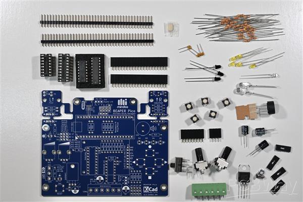
When assembling BEAPER Pico, remember that installing all of its electronic parts isn't typically necessary. Study the schematic diagram to determine which components are required for your project, and either use the parts list BOM file linked in this project to source the required electronic parts, or select the parts from this shared BEAPER Pico parts list on the Digi-Key website.
Assembling BEAPER Pico
Assembling BEAPER Pico, like most through-hole circuit boards, is easiest to do by installing the lowest profile parts first. Start by soldering all of the resistors needed for your configuration, then add the pushbuttons, and, if you're building the robot configuration, the DIP IC sockets. Next, move up to the capacitors, LEDs, headers, header sockets, regulator, power switch, and the other components you need to complete your BEAPER Pico build.

The only components that should not be installed during PCB assembly are the floor sensor LEDs and phototransistors used for making line-following or floor-sensing robots. It's important to install these into their sensor modules only after the robot design has been finalized so that they can be installed at the proper height and in the location that will provide the best sensitivity for detecting either the floor or a line.
You can find detailed, step-by-step assembly instructions for the PCB on the assembling BEAPER Pico web page.
Making robots with BEAPER Pico
The BEAPER Pico PCB integrates a motor driver IC, a screw terminal strip to connect a battery holder and two DC motors, and pre-wired optical floor and line sensor modules, making it exceptionally easy for beginners to create a variety of simple robots. The addition of a 4-pin header socket allows a commonly available HC-SR04P ('P' denotes the 3.3V version of the common 5V HC-SR04) ultrasonic SONAR distance sensor module to be plugged directly onto the PCB too, without needing a special mount.
The simplest and quickest to build robot design can be created mounting BEAPER Pico, two inexpensive and low-current gear motors, and a battery holder onto a base made from a piece of wood, MDF, or acrylic. If the optical floor sensors circuits will be used, holes drilled through the base can house their LEDs and phototransistors – the ones shown in the parts list work well when their ends are positioned approximately 1cm from the floor.
The LEDs and phototransistors soldered into the small, break-away optical sensor circuit modules on the BEAPER Pico PCB connect directly to the on-board Raspberry Pi Pico microcontroller's I/O pins while the modules remain attached. If they need to be positioned in different locations for your robot design, it's easy to snap them off the main of the PCB and mount them separately. After removing the sensor modules, they can be re-connected to the main BEAPER Pico PCB with either header pins soldered into headers H9-H12 along with socket extension cables, or by soldering wires between the sensor modules and the BEAPER Pico PCB. This allows the sensors to be positioned in front of the drive wheels for a floor sensing robot, or in the middle of the robot chassis to make a line-following robot.

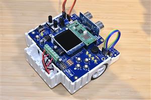
A 3D-printed BEAPER Bot chassis holds a BEAPER Pico circuit while an optical sensor module PCB, which was snapped off the main BEAPER Pico PCB and installed into its own sensor mount, is being attached to the BEAPER Bot. The floor sensor module will have its LED and phototransistor reconnected to the main BEAPER Pico PCB using short extension cables plugged into the header pins.
BEAPER Bot
A 3D-printable BEAPER Bot chassis has been developed to hold the BEAPER Pico, a 4 AA battery holder, two low current N20 gear motors with plastic drive wheels, and a roller ball castor. Using alkaline or rechargeable NiMH batteries reduces the classroom safety risk posed by LiPo batteries and eliminates the need for an on-board charging circuit. The best part – all of the chassis components clip, snap, or slide together so learners will never lose small screws, nuts, and bolts!
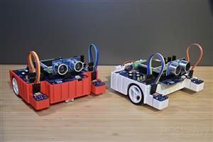
The chassis is designed to mount the BEAPER Pico PCB in either a front-drive or a rear-drive layout, which allows users to choose the best option for their style of robot. The chassis and all of its components have been designed in TinkerCad to make it easy for students (even in schools using Chromebooks) to modify the design and to create accessories and other add-ons and mounts for it.
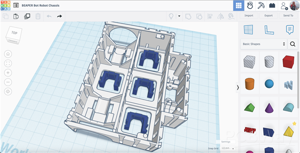
The image shows the BEAPER Bot chassis design with four motor mounting clips in TinkerCad. Links to all of the Tinkercad BEAPER Bot parts will be posted on the mirobo.tech website soon.
Introductory Learning Activities
Introductory learning activities are being developed using MicroPython. These will be designed to give beginners an understanding of all of the fundamental programming concepts they would need to understand and apply in order to control their own simple robots. Each learning activity will have an example program to introduce a major topic, guided exploration of related concepts that expand on the topic or apply the concepts in a different way, and one or more programming challenges to engage students in applying their learning in a fun way.
The preliminary Introductory Learning Activities and their programming challenges are:
Activity 1 - Input and output programs (challenge: bicycle turn signals)
Activity 2 - Constants and variables (challenge: two player rapid clicker game)
Activity 3 - Loops and PWM (challenges: LED brightness and sound effects)
Activity 4 - Creating and using functions (challenges: level indicator, number conversion)
Activity 5 - Analog input and output (challenges: robot line following)
BEAPER Pico 0.1: A (Prototype) Beginner Electronics and Programming Educational Robot for Raspberry Pi Pico
*PCBWay community is a sharing platform. We are not responsible for any design issues and parameter issues (board thickness, surface finish, etc.) you choose.


- Comments(0)
- Likes(1)
More by John Rampelt
-
 BEAPER Pico 0.1: A (Prototype) Beginner Electronics and Programming Educational Robot for Raspberry Pi Pico
BackgroundI have been teaching high school electronics and computer technology courses for over thir...
BEAPER Pico 0.1: A (Prototype) Beginner Electronics and Programming Educational Robot for Raspberry Pi Pico
BackgroundI have been teaching high school electronics and computer technology courses for over thir...
-
 CHRP4 Beginner Robotics Developer Board
CHRP4 OverviewCHRP4 (Common Hardware Robotics Project - version 4) is beginner-friendly microcontrol...
CHRP4 Beginner Robotics Developer Board
CHRP4 OverviewCHRP4 (Common Hardware Robotics Project - version 4) is beginner-friendly microcontrol...
-
 BEAPER Bot Robot Chassis
BEAPER BotBEAPER (Beginner Electronics and Programming Educational Robot) Bot is a 3D-printable BEAP...
BEAPER Bot Robot Chassis
BEAPER BotBEAPER (Beginner Electronics and Programming Educational Robot) Bot is a 3D-printable BEAP...
-
 BEAPER Nano 1.0: the Beginner Electronics and Programming Educational Robot circuit for Arduino Nano ESP32
When the Arduino Nano ESP32 was released with a combination of a fast, powerful microcontroller, lot...
BEAPER Nano 1.0: the Beginner Electronics and Programming Educational Robot circuit for Arduino Nano ESP32
When the Arduino Nano ESP32 was released with a combination of a fast, powerful microcontroller, lot...
-
 BEAPER Nano (Beginner Electronics and Programming Educational Robot) for Arduino Nano ESP32
Note: This is the first prototype BEAPER Nano circuit. See the newest BEAPER Nano 1.0 circuit. BEAPE...
BEAPER Nano (Beginner Electronics and Programming Educational Robot) for Arduino Nano ESP32
Note: This is the first prototype BEAPER Nano circuit. See the newest BEAPER Nano 1.0 circuit. BEAPE...
-
 BPStick (Breadboard Power Stick) - 5V through hole version
When schools start teaching STEM programs, or hobbyists embark on learning electronics, one of their...
BPStick (Breadboard Power Stick) - 5V through hole version
When schools start teaching STEM programs, or hobbyists embark on learning electronics, one of their...
-
 UPS (USB Power Stick) breadboard power adapter
When schools start teaching STEM programs, or hobbyists embark on learning electronics, one of their...
UPS (USB Power Stick) breadboard power adapter
When schools start teaching STEM programs, or hobbyists embark on learning electronics, one of their...
-
 ARPS – A Beginner Arduino®-compatible Robot Project Shield
ARPS OverviewARPS (Arduino®-compatible Robot Project Shield) is beginner-friendly add-on shield for ...
ARPS – A Beginner Arduino®-compatible Robot Project Shield
ARPS OverviewARPS (Arduino®-compatible Robot Project Shield) is beginner-friendly add-on shield for ...
-
 UBMP4 Beginner Microcontroller Development Board
UBMP4 OverviewUBMP4 (USB-based Beginner Multipurpose Project - version 4) is beginner-friendly micro...
UBMP4 Beginner Microcontroller Development Board
UBMP4 OverviewUBMP4 (USB-based Beginner Multipurpose Project - version 4) is beginner-friendly micro...
-
-
-
-
Tester for Touch Screen Digitizer without using microcontroller
330 2 2 -
Audio reactive glow LED wristband/bracelet with NFC / RFID-Tags
310 0 1 -
-
-


