


|
arduino IDEArduino
|
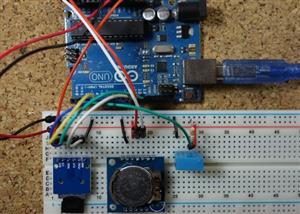
Attendance System With Arduino & Rfid Tag
MFRC522 RFID Reader
In this project we’re using the MFRC522 RFID reader and that’s the one we recommend you to get (although this project may also be compatible with other RFID readers).
RFID means radio-frequency identification. RFID uses electromagnetic fields to transfer data over short distances and it’s useful to identify people, to make transactions, etc.
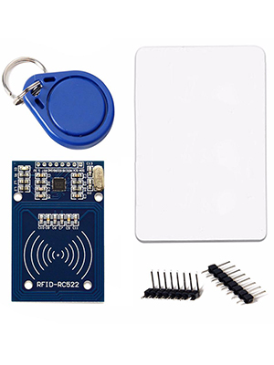
An RFID system needs tags and a reader:
Tags are attached to the object to be identified, in this example we have a keychain and an electromagnetic card. Some stores also use RFID tags in their products’ labels to identify them. Each tag has its own unique identification (UID).
The MFRC522 RFID reader works at 3.3V and it can use SPI or I2C communication. The library we’re going to use to control the RFID reader only supports SPI, so that’s the communication protocol we’re going to use.
To learn more about the RFID reader with the Arduino read: Security Access using MFRC522 RFID Reader with Arduino
Installing the MFRC522 library
This project uses the MFRC522.h library to control the RFID reader. This library doesn’t come installed in Arduino IDE by default, so you need to install it. Go to Sketch > Include library > Manage libraries and search for MFRC522 or follow the next steps:
Click here to download the MFRC522 library. You should have a.zip folder in your Downloads folder.
Unzip the.zip folder and you should get RFID-master folder
Rename your folder from RFID-master to RFID
Move the RFID folder to your Arduino IDE installation libraries folder
Finally, re-open your Arduino IDE
CODE
#include <MFRC522.h> // for the RFID
#include <SPI.h> // for the RFID and SD card module
#include <SD.h> // for the SD card
#include <RTClib.h> // for the RTC
// define pins for RFID
#define CS_RFID 10
#define RST_RFID 9
// define select pin for SD card module
#define CS_SD 4
// Create a file to store the data
File myFile;
// Instance of the class for RFID
MFRC522 rfid(CS_RFID, RST_RFID);
// Variable to hold the tag's UID
String uidString;
// Instance of the class for RTC
RTC_DS1307 rtc;
// Define check in time
const int checkInHour = 9;
const int checkInMinute = 5;
//Variable to hold user check in
int userCheckInHour;
int userCheckInMinute;
// Pins for LEDs and buzzer
const int redLED = 6;
const int greenLED = 7;
const int buzzer = 5;
void setup() {
// Set LEDs and buzzer as outputs
pinMode(redLED, OUTPUT);
pinMode(greenLED, OUTPUT);
pinMode(buzzer, OUTPUT);
// Init Serial port
Serial.begin(9600);
while(!Serial); // for Leonardo/Micro/Zero
// Init SPI bus
SPI.begin();
// Init MFRC522
rfid.PCD_Init();
// Setup for the SD card
Serial.print("Initializing SD card...");
if(!SD.begin(CS_SD)) {
Serial.println("initialization failed!");
return;
}
Serial.println("initialization done.");
// Setup for the RTC
if(!rtc.begin()) {
Serial.println("Couldn't find RTC");
while(1);
}
else {
// following line sets the RTC to the date & time this sketch was compiled
rtc.adjust(DateTime(F(__DATE__), F(__TIME__)));
}
if(!rtc.isrunning()) {
Serial.println("RTC is NOT running!");
}
}
void loop() {
//look for new cards
if(rfid.PICC_IsNewCardPresent()) {
readRFID();
logCard();
verifyCheckIn();
}
delay(10);
}
void readRFID() {
rfid.PICC_ReadCardSerial();
Serial.print("Tag UID: ");
uidString = String(rfid.uid.uidByte[0]) + " " + String(rfid.uid.uidByte[1]) + " " +
String(rfid.uid.uidByte[2]) + " " + String(rfid.uid.uidByte[3]);
Serial.println(uidString);
// Sound the buzzer when a card is read
tone(buzzer, 2000);
delay(100);
noTone(buzzer);
delay(100);
}
void logCard() {
// Enables SD card chip select pin
digitalWrite(CS_SD,LOW);
// Open file
myFile=SD.open("DATA.txt", FILE_WRITE);
// If the file opened ok, write to it
if (myFile) {
Serial.println("File opened ok");
myFile.print(uidString);
myFile.print(", ");
// Save time on SD card
DateTime now = rtc.now();
myFile.print(now.year(), DEC);
myFile.print('/');
myFile.print(now.month(), DEC);
myFile.print('/');
myFile.print(now.day(), DEC);
myFile.print(',');
myFile.print(now.hour(), DEC);
myFile.print(':');
myFile.println(now.minute(), DEC);
// Print time on Serial monitor
Serial.print(now.year(), DEC);
Serial.print('/');
Serial.print(now.month(), DEC);
Serial.print('/');
Serial.print(now.day(), DEC);
Serial.print(' ');
Serial.print(now.hour(), DEC);
Serial.print(':');
Serial.println(now.minute(), DEC);
Serial.println("sucessfully written on SD card");
myFile.close();
// Save check in time;
userCheckInHour = now.hour();
userCheckInMinute = now.minute();
}
else {
Serial.println("error opening data.txt");
}
// Disables SD card chip select pin
digitalWrite(CS_SD,HIGH);
}
void verifyCheckIn(){
if((userCheckInHour < checkInHour)||((userCheckInHour==checkInHour) && (userCheckInMinute <= checkInMinute))){
digitalWrite(greenLED, HIGH);
delay(2000);
digitalWrite(greenLED,LOW);
Serial.println("You're welcome!");
}
else{
digitalWrite(redLED, HIGH);
delay(2000);
digitalWrite(redLED,LOW);
Serial.println("You are late...");
}
}
Preparing the SD card
The first step when using the SD card module with Arduino is formatting the SD card as FAT16 or FAT32. Follow the instructions below.
1) To format the SD card, insert it in your computer. Go to My Computer and right click on the SD card. Select Format as shown in figure below.

2) A new window pops up. Select FAT32, press Start to initialize the formatting process and follow the onscreen instructions.

Testing the SD card module
(This step is optional. This is an additional step to make sure the SD card module is working properly.)
Insert the formatted SD card in the SD card module.
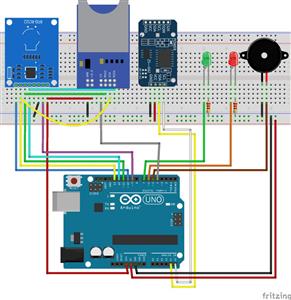
Connect the SD card module to the Arduino as shown in the circuit schematics below or check the pinout table.
Note: depending on the module you’re using, the pins may be placed in a different location.
Uploading CardInfo sketch
To make sure everything is wired correctly and the SD card is working properly, in the Arduino IDE window go to File> Examples > SD > CardInfo.
Upload the code to your Arduino board. Make sure you have the right board and COM port selected.
Open the Serial Monitor at a baud rate of 9600 and the SD card information will be displayed. If everything is working properly you’ll see a similar message on the serial monitor.

RTC (Real Time Clock) module
To keep track of time, we’re using the SD1307 RTC module. However, this project works just fine with the DS3231, which is very similar. One main difference between them is the accuracy. The DS3231 is much more accurate than the DS1307. The figure below shows the SD1307 model.

The module has a backup battery installed. This allows the module to retain the time, even when it’s not being powered up.
This module uses I2C communication and we’ll use the RTCLib.h library to read the time from the RTC.
To learn more about the DS1307 real time clock with the Arduino read: Guide for Real Time Clock (RTC) Module with Arduino (DS1307 and DS3231)
Grabbing the SD Card data
To check the data saved on the SD card, remove it from the SD card module and insert it on your computer.
Open the SD card folder and you should have a file called DATA.txt.

Open the file using a text editor. You’ll have something as follows:

Notice that each value is separated by commas. This makes it easier if you want to import this data to Excel, Google Sheets, or other data processing software.

Attendance System With Arduino & Rfid Tag


Raspberry Pi 5 7 Inch Touch Screen IPS 1024x600 HD LCD HDMI-compatible Display for RPI 4B 3B+ OPI 5 AIDA64 PC Secondary Screen(Without Speaker)
BUY NOW


- Comments(0)
- Likes(2)
 More by Engineer
-
 Esp8266 Task Publisher
In this project you’re going to build an ESP8266 Wi-Fi Button that can trigger any home automation e...
Esp8266 Task Publisher
In this project you’re going to build an ESP8266 Wi-Fi Button that can trigger any home automation e...
-
 ESP32 Avanced Weather Station
Introducing the BME280 Sensor ModuleThe BME280 sensor module reads temperature, humidity, and pressu...
ESP32 Avanced Weather Station
Introducing the BME280 Sensor ModuleThe BME280 sensor module reads temperature, humidity, and pressu...
-
 Esp32 Pir Sensor Time Interrupts
Introducing InterruptsTo trigger an event with a PIR motion sensor, you use interrupts. Interrupts a...
Esp32 Pir Sensor Time Interrupts
Introducing InterruptsTo trigger an event with a PIR motion sensor, you use interrupts. Interrupts a...
-
 Multiple Temperature Sensor Data Logging With Esp32
Introducing the DS18B20 Temperature SensorThe DS18B20 temperature sensor is a 1-wire digital tempera...
Multiple Temperature Sensor Data Logging With Esp32
Introducing the DS18B20 Temperature SensorThe DS18B20 temperature sensor is a 1-wire digital tempera...
-
 IOT Button
IFTTTFor this project we’re going to use a free service called IFTTT that stands for If This Than Th...
IOT Button
IFTTTFor this project we’re going to use a free service called IFTTT that stands for If This Than Th...
-
 Wemos D1 Multishield Arduino
Project OverviewThe shield consists of a temperature sensor, a motion sensor, an LDR, and a 3 pin so...
Wemos D1 Multishield Arduino
Project OverviewThe shield consists of a temperature sensor, a motion sensor, an LDR, and a 3 pin so...
-
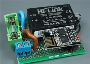 Motion Detection Alarm
ABOUT THIS PROJECTIn this project we’ll modify a commercial motion sensor (powered with mains voltag...
Motion Detection Alarm
ABOUT THIS PROJECTIn this project we’ll modify a commercial motion sensor (powered with mains voltag...
-
 Iot Spirit Level
ABOUT THIS PROJECTThe gyroscope measures rotational velocity (rad/s), this is the change of the angu...
Iot Spirit Level
ABOUT THIS PROJECTThe gyroscope measures rotational velocity (rad/s), this is the change of the angu...
-
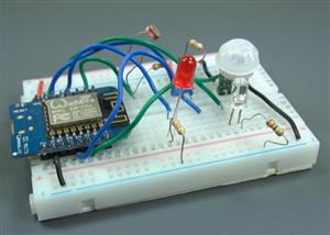
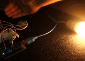 PIR Night Security Light
Parts Required:Here’s a list of the parts needed for this project:PIR Motion Sensor 220V (or 110V PI...
PIR Night Security Light
Parts Required:Here’s a list of the parts needed for this project:PIR Motion Sensor 220V (or 110V PI...
-
 Arduino Temperature Logger With Sd Card
Parts requiredHere’s a complete list of the parts required for this project:Arduino UNO – read Best ...
Arduino Temperature Logger With Sd Card
Parts requiredHere’s a complete list of the parts required for this project:Arduino UNO – read Best ...
-
 Arduino Location Tracker
Introducing the NEO-6M GPS ModuleThe NEO-6M GPS module is shown in the figure below. It comes with a...
Arduino Location Tracker
Introducing the NEO-6M GPS ModuleThe NEO-6M GPS module is shown in the figure below. It comes with a...
-
 Attendance System With Arduino & Rfid Tag
MFRC522 RFID ReaderIn this project we’re using the MFRC522 RFID reader and that’s the one we recomme...
Attendance System With Arduino & Rfid Tag
MFRC522 RFID ReaderIn this project we’re using the MFRC522 RFID reader and that’s the one we recomme...
-
-
ARPS-2 – Arduino-Compatible Robot Project Shield for Arduino UNO
2280 0 5 -
A Compact Charging Breakout Board For Waveshare ESP32-C3
2761 3 7 -
AI-driven LoRa & LLM-enabled Kiosk & Food Delivery System
2959 2 0 -
-
-
-
ESP32-C3 BLE Keyboard - Battery Powered with USB-C Charging
3001 0 2 -


