


A DIY Smart Safety Module for Household Gas Regulators
Story
HELLO EVERYONE !!
I'm excited to share this project with you. Today, I'm documenting a system that's actively protecting my family.
This isn't a polished corporate product or a perfectly planned research project. It's a real story of late nights, burnt fingers from soldering irons, failed 3D prints, and that incredible moment when everything finally clicked together at 2 AM. SafeGuard was born from genuine fear after witnessing my neighbor's kitchen fire, built under intense time pressure, and refined through real-world testing in my own home.
Let's dive into how a project became a potentially life-saving device that my mother now trusts more than her own memory. Welcome to the SafeGuard story.
Why I Built This
Three months ago, my neighbour's kitchen caught fire. A slow LPG leak during the night, an early morning spark from the refrigerator compressor, and suddenly their home was engulfed in flames. They escaped, thankfully, but the incident shook our entire apartment building.
Most LPG accidents happen because we can't see or smell small leaks until it's too late. We trust a manual regulator knob and our own memory to turn off the gas before sleeping.
I realized I had the skills to build something better. Something that could detect leaks instantly, cut off gas supply automatically, and alert families before disaster strikes. The idea consumed me. I sketched designs during lectures, calculated load cell placements at midnight, and did some research.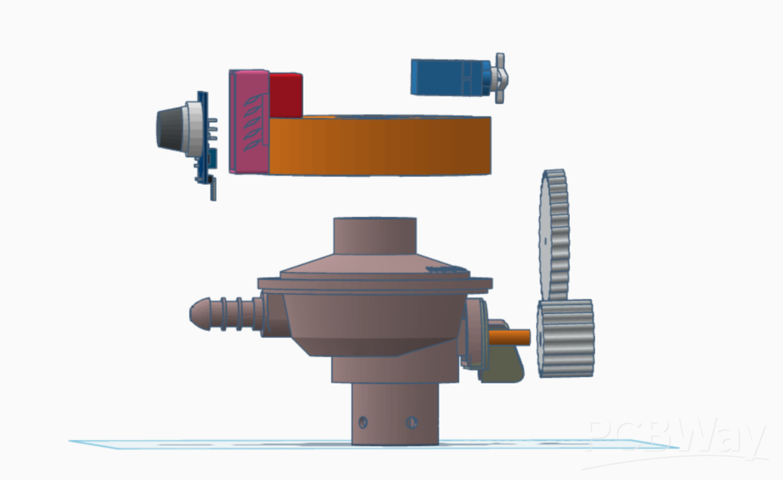

The Problem Statement
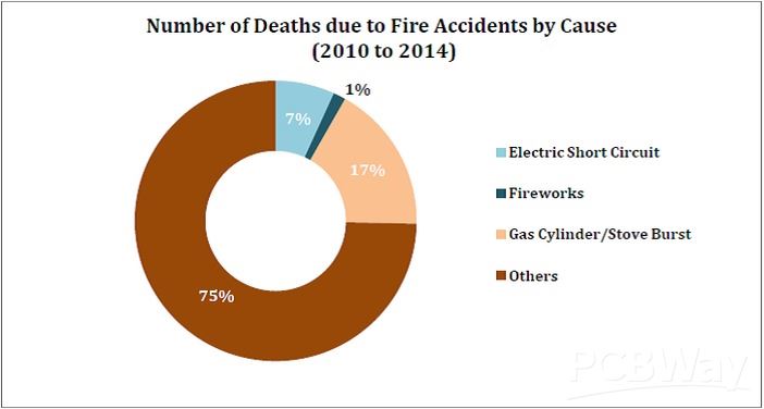
Every year, thousands of homes experience LPG-related accidents. In India alone, over Thousands of LPG cylinder explosions are reported annually, with countless more unreported incidents. The numbers are staggering, but behind each statistic is a family, a home, a life changed forever.
Gas leaks are invisible killers. LPG is heavier than air, so it settles at floor level where children and pets play. By the time you smell the odorant added to LPG, the concentration might already be dangerous. A single spark—from a light switch, a phone charger, static electricity can trigger catastrophe.
The Solution: SafeGuard Overview
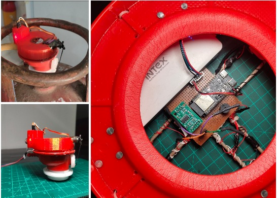
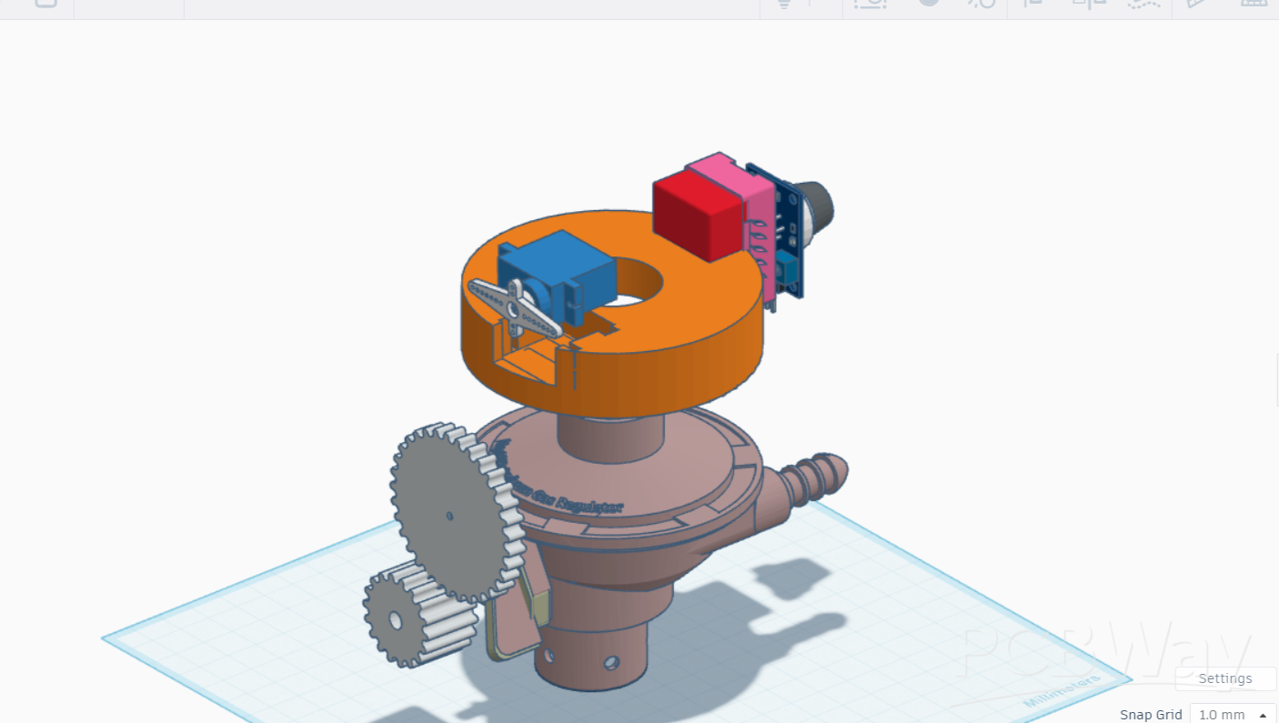
SafeGuard transforms your ordinary LPG regulator into an intelligent safety system. At its core is an ESP32-C6 microcontroller that constantly monitors three critical parameters: gas leak presence, cylinder weight, Valve Status and time of day.
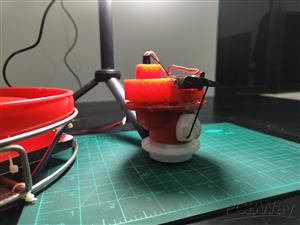
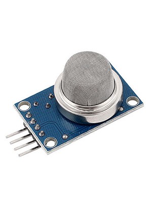
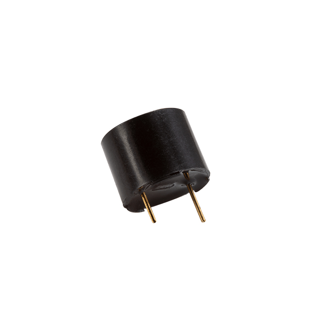
The MQ-2 sensor continuously samples the air around your cylinder, detecting even minor LPG concentrations. When it senses danger, the system reacts in under two seconds a servo motor physically turns the regulator valve to the off position, cutting the gas supply completely. Simultaneously, a buzzer sounds an alarm, and your phone receives an instant notification, even if you're away from home.
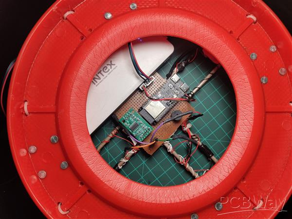
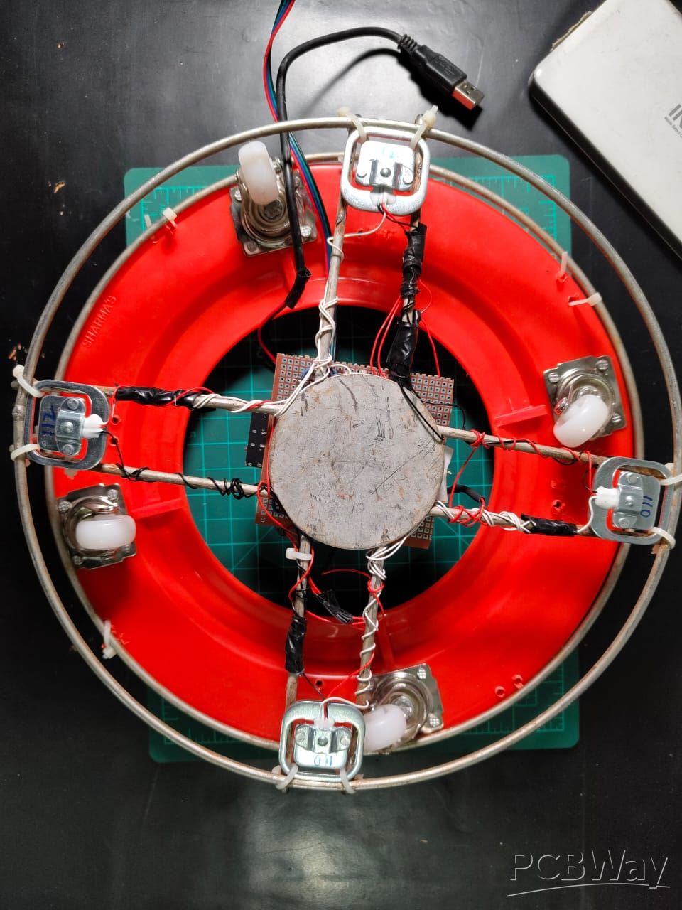
Four load cells positioned beneath the cylinder provide precise weight measurements, calculating exactly how much gas remains. You'll know whether you have enough gas for the week or if you need to order a refill soon. No more surprises in the middle of cooking.
The nighttime auto-shutoff feature adds an extra layer of protection. During sleeping hours, SafeGuard automatically closes the valve, ensuring that even if there's a leak or regulator failure, your family sleeps safely. You can override this manually through the app if needed.
Everything connects to your smartphone via Blynk. Check gas levels from your bedroom Or anywhere around the world. Turn off the supply remotely if you forgot before leaving for vacation. Get alerts about unusual consumption patterns. The power of complete control, in your pocket.
Core features
Automatic Leak Protection MQ-2 sensor detects LPG presence and triggers instant valve shutoff with alarm and phone notification
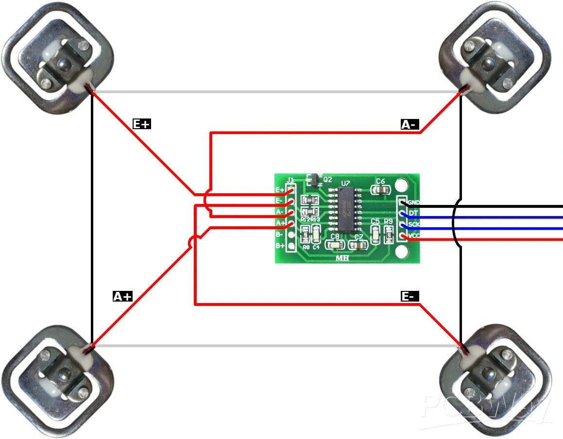
Real-Time Gas Level Monitoring Four load cells measure cylinder weight and calculate remaining gas percentage with accuracy
Smart Night Mode Automatic gas supply cutoff during sleeping hours for enhanced safety
Complete Mobile Control Blynk app integration for remote monitoring, manual valve control, and instant alerts
Emergency Response System Multi-layer alert system: buzzer alarm, LED indicator, and push notifications
Fail-Safe Design Servo-controlled mechanical valve ensures gas can be cut off even during sensor failures
Low Gas Alerts Proactive notifications when cylinder reaches preset low levels, preventing unexpected outages
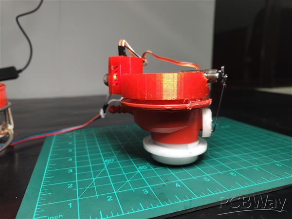
Universal Compatibility 3D-printed servo mount fits standard LPG regulators without permanent modifications
How SafeGuard Works: Complete Flow
SafeGuard's architecture revolves around the ESP32-C6 microcontroller as the brain of the system. The MQ-2 gas sensor continuously feeds analog data to the ESP32's ADC pin, while the HX711 amplifier processes signals from four load cells and communicates digitally. The ESP32 processes this information and controls outputs: the servo motor for valve actuation, buzzer for local alarms, and the onboard LED for status indication. WiFi connectivity links everything to the Blynk cloud platform, enabling remote monitoring and control.
All components share a common 5V power rail from a 2.1A power bank, with the ESP32-C6 regulating its own 3.3V logic internally. The system operates in a continuous loop—monitoring, analyzing, and responding to changes in gas concentration, cylinder weight, and user commands from the mobile app.
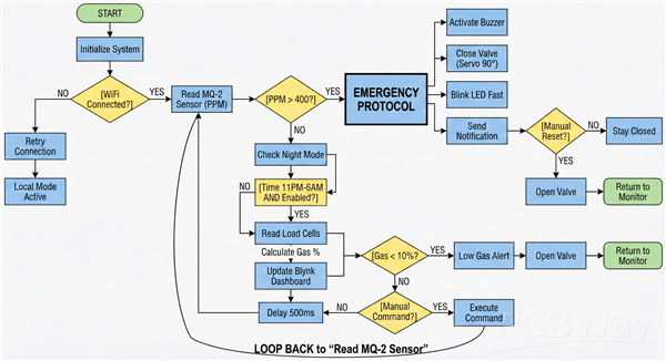
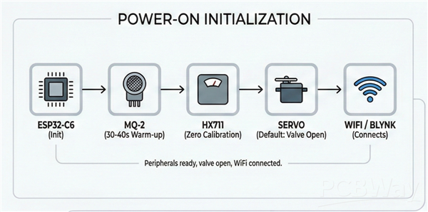
Power-On Initialization: When SafeGuard boots up, the ESP32-C6 initializes all peripherals. The MQ-2 sensor provides usable readings after just 30-40 Seconds of warm-up. The HX711 performs a zero calibration, and the servo -moves to its default position (gas valve open). WiFi connects to your home network, and the Blynk app establishes communication.
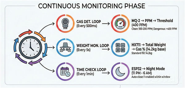
Continuous Monitoring Phase: Three parallel monitoring loops run simultaneously:
Gas Detection Loop (every 500ms): The ESP32 reads the analog voltage from MQ-2's A0 pin, converts it to PPM (parts per million), and compares it against the 400 PPM threshold. Clean air reads around 100-200 PPM, while dangerous LPG concentrations push values above 400 PPM.
Weight Monitoring Loop (every 5 seconds): The HX711 reads the combined signal from all four load cells, applies the calibration factor, and calculates total weight. Subtracting the empty cylinder weight (typically 15kg) gives the remaining gas weight. This converts to a percentage based on the standard 14.2kg fill.
Time Check Loop (every minute): The ESP32 checks the current time against the night mode schedule (11 PM - 6 AM). If enabled via the app and within this window, the system automatically closes the valve.
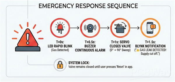
Emergency Response Sequence: When MQ-2 detects PPM levels above 400:
T+0 seconds: Gas detected, onboard LED starts rapid blinking
T+0.5 seconds: Buzzer activates with continuous alarm tone
T+1 second: Servo rotates to close valve position (0° to 90° sweep)
T+1.5 seconds: Blynk notification sent: " GAS LEAK DETECTED! Supply cut off."
System locks: Valve remains closed until user presses "Reset" button in app
Normal Operation: Under safe conditions, the app displays real-time gas percentage, current PPM reading, and valve status. Users can manually open/close the valve, toggle night mode, and adjust settings. Low gas alerts trigger automatically when levels drop below 10% (approximately 1.4kg remaining).
Rapid Prototyping & Preparation
I cleared my entire workbench. Electronics assembly demands organization—one misplaced wire or lost screw can derail hours of work.
Test Each Component before moving to the project with Example sketches to Avoid Unnecessary troubleshooting and Time waste Between the build.
Lighting matters more than you'd think. I positioned a desk light directly over the work area. PCB soldering requires seeing those tiny solder joints clearly, and shadows cause mistakes. If you wear glasses, clean them—seriously, it helps.
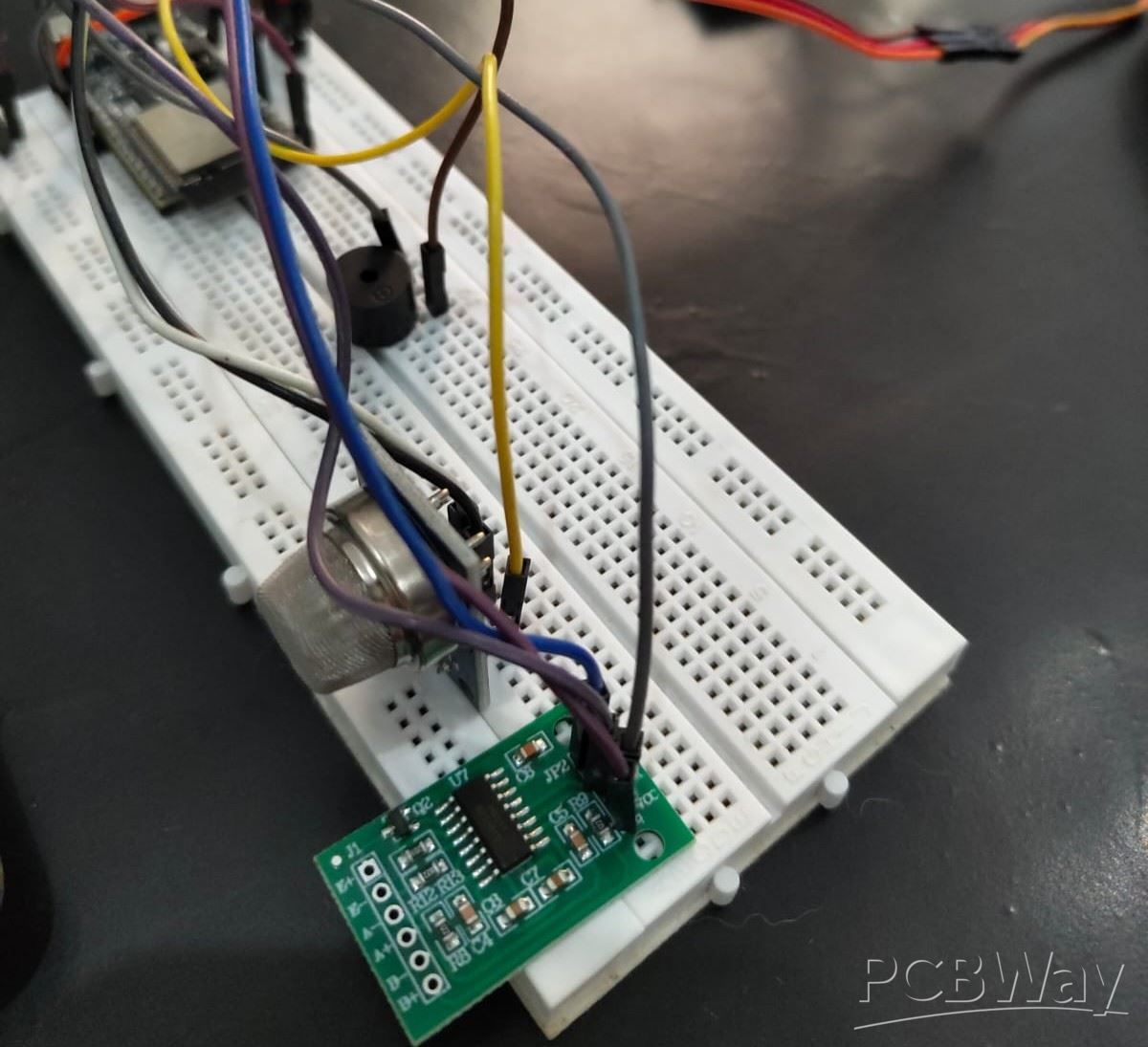
Before soldering anything permanent, I built the entire circuit on a breadboard. This let me test code and fix bugs without worrying about desoldering mistakes.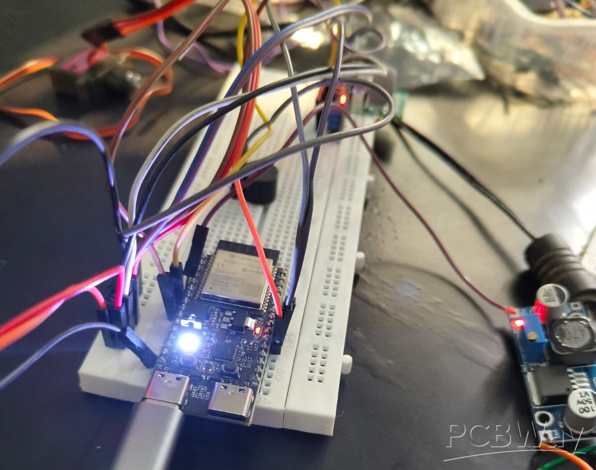
Build Process:
The build process spanned intense 3 days. I spent every available hour soldering, testing, troubleshooting, and refining. This wasn't a smooth linear process it was messy, frustrating, and deeply rewarding. I made mistakes, burned my fingers on the soldering iron twice, and nearly gave up when the load cells refused to calibrate properly on day three. But each obstacle taught me something valuable about electronics, mechanical design, and problem-solving under pressure.
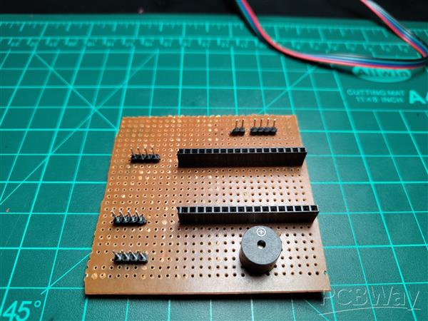
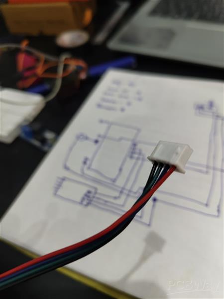
Circuit Schematic Diagram
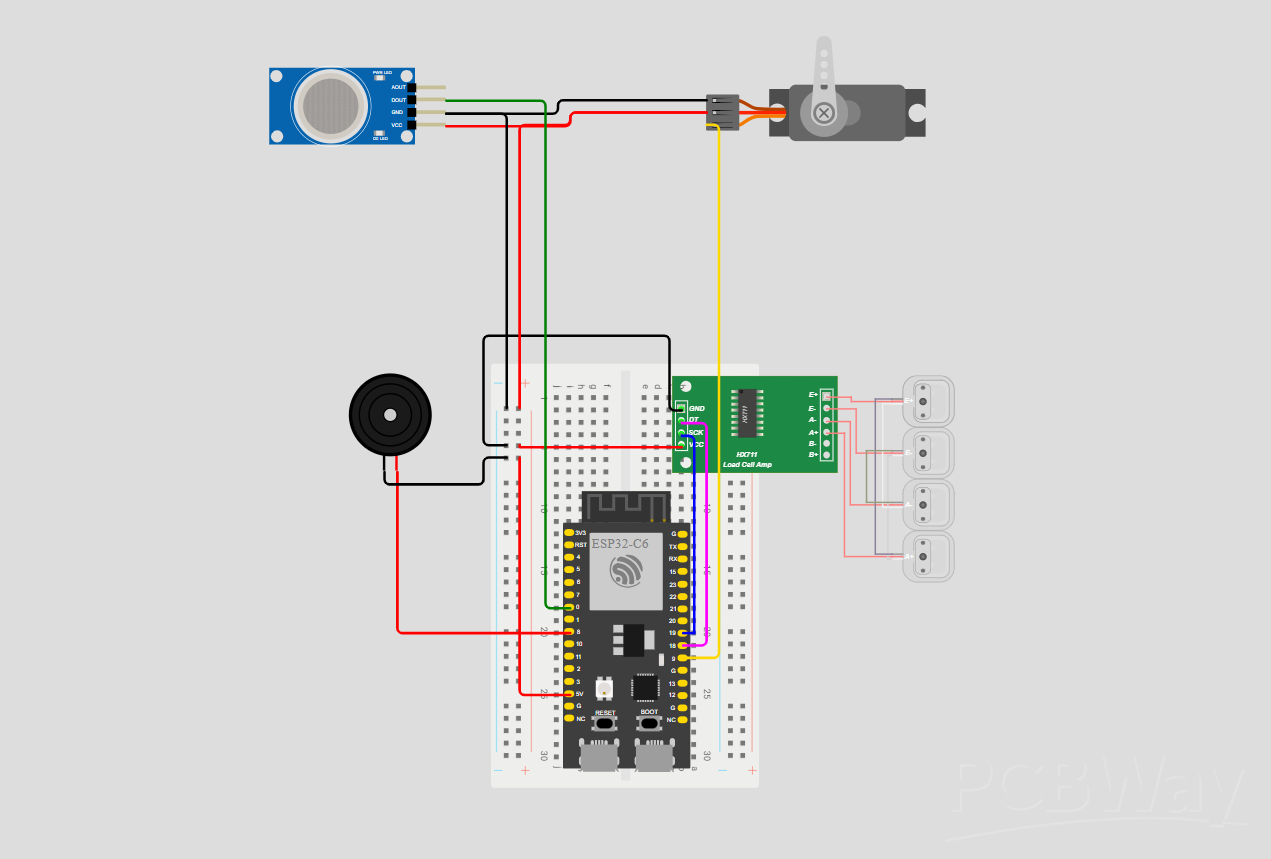
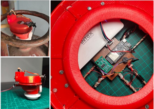
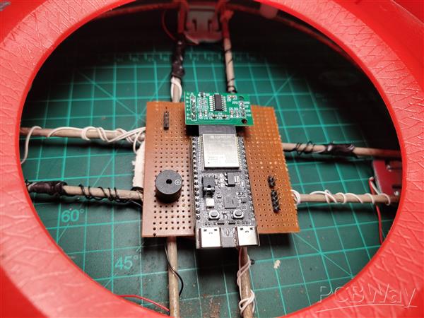
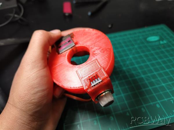
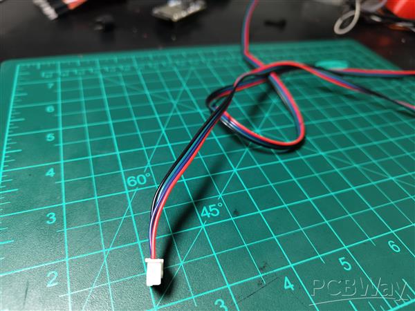
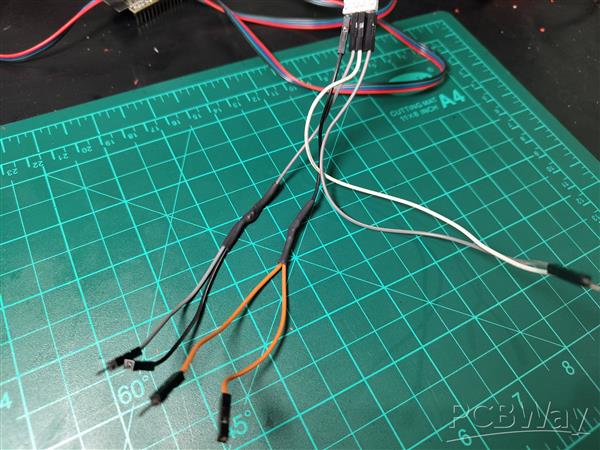
The circuit design centers on simplicity and reliability. Since I was racing against the project deadline, I hand-soldered everything on a zero PCB. I mounted male Berg strip connectors on the PCB for the MQ-2 sensor and servo—these components live on top of the regulator, so I needed a detachable cable connection. I repurposed a stepper motor cable for this, which had the perfect wire gauge and length.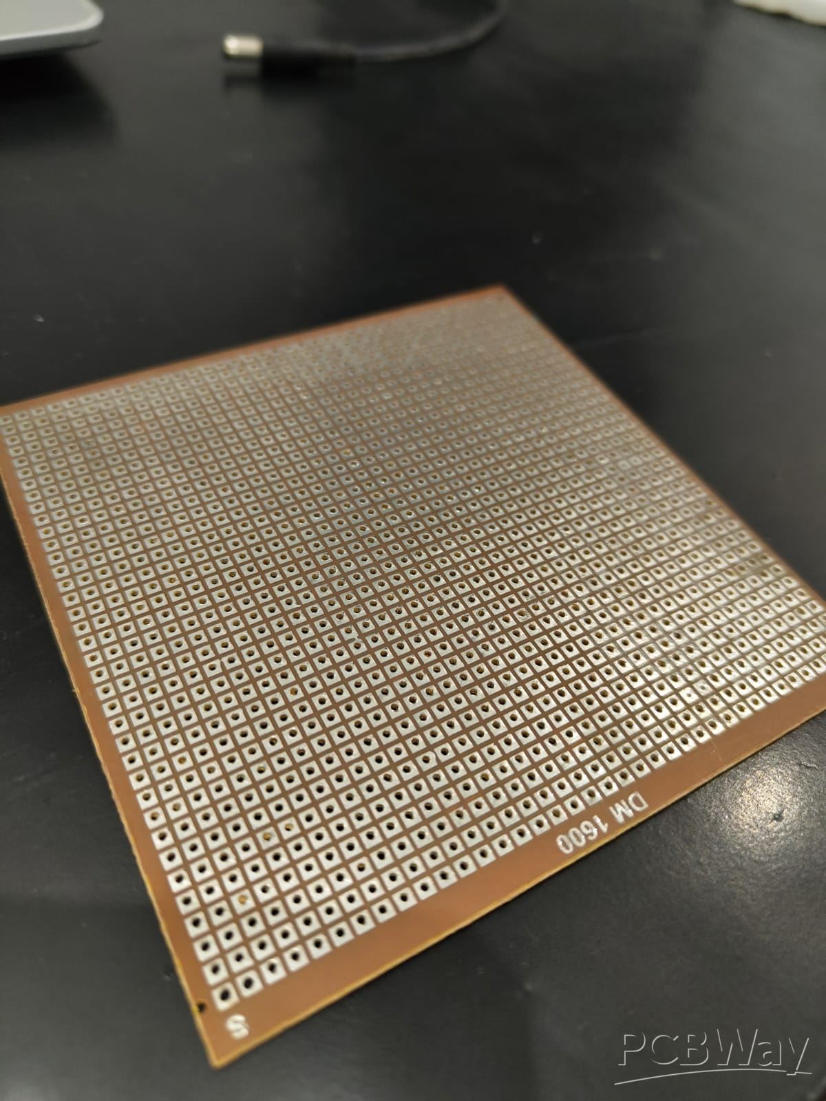
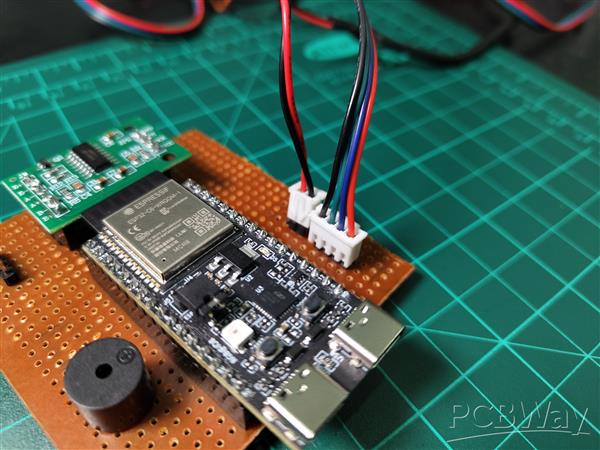
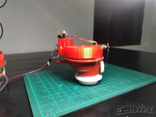
Connectivity from top Mount To Base
I'm using Stepper motor Cable TO connect the regulator mount with the microcontroller in the base. I Created Simple PNP Mechanism For Better Prototyping and Ease of use
Key Design Decisions:
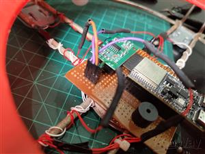
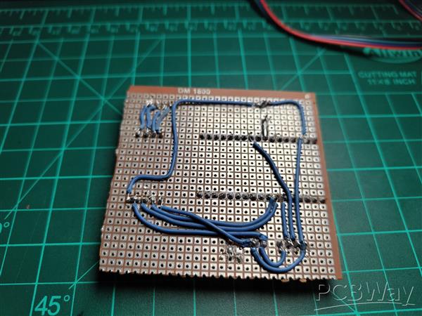
Common Ground: All grounds tie to a thick copper bus I soldered along the PCB edge
5V Distribution: Another copper bus carries 5V to all components
Signal Isolation: Kept MQ-2 analog traces away from servo PWM wire to minimize noise
Strain Relief: Used hot glue on Berg strip connections to prevent cable stress damage
Power Distribution: The 5V power bank connects directly to the common power bus. The ESP32-C6 has an onboard 3.3V regulator that powers its internal logic. The MQ-2 sensor module has its own onboard regulator, so it safely accepts 5V input. The servo and buzzer run directly on 5V.
Important Note on Servo Power: I'm powering the servo directly from the same 5V rail as the ESP32. This works with my 2.1A power bank, but during servo rotation, there can be voltage dips that might cause the ESP32 to brown out or reset. I strongly recommend adding a 1000µF electrolytic capacitor across the servo's power pins (positive to 5V, negative to GND) to smooth these current spikes. I didn't add one due to time constraints, but it's a best practice for servo-based projects.
Overall Design Overview


A DIY Smart Safety Module for Household Gas Regulators
Project images are for reference only. Actual production is based on the manufacturing files on the project page.
Please review the designer's notes (e.g., PCB thickness) and select the appropriate options.
PCBWay is not responsible
for issues caused by unsuitable parameter selections.
For more important ordering information, please refer to
Read More


Raspberry Pi 5 7 Inch Touch Screen IPS 1024x600 HD LCD HDMI-compatible Display for RPI 4B 3B+ OPI 5 AIDA64 PC Secondary Screen(Without Speaker)
BUY NOW


- Comments(2)
- Likes(1)
More by Barely Works
-
Programmable Mist Maker - XIAO / QT PY Extension
1177 2 1 -
RadioHAT - Raspberry Pi radio development platform
980 0 2 -
-
-
-
-
ARPS-2 – Arduino-Compatible Robot Project Shield for Arduino UNO
3395 0 6 -
A Compact Charging Breakout Board For Waveshare ESP32-C3
4020 3 8 -
AI-driven LoRa & LLM-enabled Kiosk & Food Delivery System
4414 2 2


