AMIGA 1200 KEYBOARD HEADER PCB (IDC CONNECTOR VERSION)
AMIGA 1200 KEYBOARD HEADER PCB FOR PCB MEMBRANE (IDC CONNECTOR VERSION)
Hello,
After sharing a PCB membrane replacement for Amiga 500 some of my friends asked me to make a similar PCB membrane for Amiga 1200. But I do not have an A1200. My friend Orhan gave me an A1200 keyboard to use for this project. I drew the membrane and my another friend Turgay ordered PCBs and tested. He aproved the GERBERs are OK and PCBs worked as they should. (Many thanks to Orhan and Turgay)
I designed the A1200 membrane and headers in two versions. One version is IDC version the other version is FFC version. IDC version is through-hole technology (THT), FFC version is surface mounted technology (SMT). IDC version membrane must be used with IDC Header and FFC version membrane must be used with FFC Header.
Both IDC and FFC versions consist of 3 main parts.
1) Keyboard membrane PCB - Thickness : 0.6 mm Surface Finish : Immersion gold (ENIG)
2) Header PCB
3) Cable between header PCB and keyboard membrane PCB
The most important difference between IDC and FFC versions is; the IDC version membrane connector must be soldered after being placed on the metal housing of the Amiga 1200 keyboard. In the IDC version, once the connector has been soldered, the connector have to be desoldered so that the PCB membrane can be separated from the metal part. For this reason, it is not possible to sell the IDC version membrane as a complete ready to use. But FFC version can be sold as ready to use.
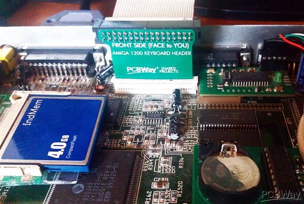
I drew this PCB for Amiga 1200 to use with the PCB keyboard membrane. This PCB plugs into the keyboard connector on the A1200 motherboard and is used to assist the connection between the PCB keyboard membrane and the A1200 motherboard.
Layers : 2 Layers PCB
Material : FR-4
Thickness : Header PCB thickness should be 1mm or 0.6mm depending on how you will use the motherboard keyboard connector. If you want to use it by removing the clamping part of the keyboard connector on the motherboard, 1mm thickness is suitable. My friend Turgay said that he thought it was more efficient that way. If you want to use the keyboard connector on the motherboard without removing the clamping part, 0.6mm thickness is suitable, but in this case you have to insert the locking mechanism very carefully and slowly. Otherwise, the plastic part may break easily.
This PCB is prepared for use with an ordinary 34 Pin male IDC connector, so that; the connection between the A1200 motherboard and the keyboard can be established with an ordinary flat Floppy disk drive cable.
With this header, it is also possible to use an Amiga 500 keyboard on an Amiga 1200. (by soldering 31 wires to under the A500 keyboard PCB connector.) ;)
Make sure your keyboard membrane is defective before ordering this PCB. Sometimes the problem is the conductive rubbers under the keys, and you can easily fix this with a soft 4B pencil. You only need to completely scribble the conductive rubber itself and the membrane's pads with a 4B pencil.
If you are using a 1mm thick Header PCB, you have to remove the clamping part of the keyboard connector on the motherboard. (My friend Turgay said he thinks 1mm thickness is better than 0.6mm thickness for header PCB.)
If you are using a 0.6mm thick Header PCB, with the A1200 motherboard keyboard connector locking system in the unlocked position, gently push the PCB into the connector. You may need to shake the PCB a little if it's having trouble getting in. Next, close the lock of the connector by pushing it slowly.
Do not rush and be careful while following these procedures, ask for help from a knowledgeable person at a point you need asistance.
For testing Amiga keyboard, you can download the "Amiga Test Kit" ADF disk image from this link.
https://github.com/keirf/Amiga-Stuff . Many thanks to Keir Fraser (keirf)
Components:
34pin DC3 2.54mm Pitch Jtag Isp Male Socket Straight IDC connector (2x17 Male Box Header)
34pin 2.54mm Pitch (2x17) female-female IDC cable
AMIGA 1200 KEYBOARD MEMBRANE REPLACEMENT (IDC VERSION)
Ps. Solder the IDC box connector in the correct side and correct direction, with the notch facing down, as in the photos.
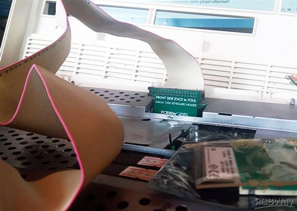
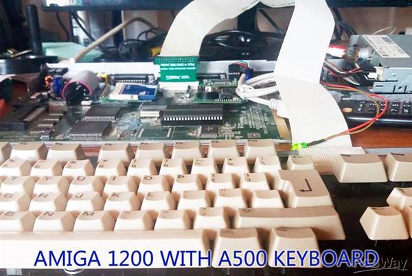
Gerber files and component list are subject to change without notice. Before paying for the PCBs, be sure to update your orders!
As you can see I have uploaded many projects and I am still working on new projects. If you have any questions, please look for answers online. Unless I specify explicitly, all my projects are tested and confirmed to work under normal circumstances before being shared. I'm sorry I didn't have enough time to answer all the questions.
Use this PCB at your own risk !
Have fun
Thank you.
C64istanbul
AMIGA 1200 KEYBOARD HEADER PCB (IDC CONNECTOR VERSION)
*PCBWay community is a sharing platform. We are not responsible for any design issues and parameter issues (board thickness, surface finish, etc.) you choose.

Raspberry Pi 5 7 Inch Touch Screen IPS 1024x600 HD LCD HDMI-compatible Display for RPI 4B 3B+ OPI 5 AIDA64 PC Secondary Screen(Without Speaker)
BUY NOW- Comments(2)
- Likes(7)
-
 Jan Lunitz
Jun 08,2025
-
 Roman Kovář
Apr 06,2024
-
 Francisco Meza
Mar 07,2024
-
 Engineer
Nov 18,2023
-
 freesofia
Nov 10,2023
-
 Jessica L Petersen
Jul 10,2023
-
 Özay Turay
May 21,2023
- 1 USER VOTES
- YOUR VOTE 0.00 0.00
- 1
- 2
- 3
- 4
- 5
- 6
- 7
- 8
- 9
- 10
- 1
- 2
- 3
- 4
- 5
- 6
- 7
- 8
- 9
- 10
- 1
- 2
- 3
- 4
- 5
- 6
- 7
- 8
- 9
- 10
- 1
- 2
- 3
- 4
- 5
- 6
- 7
- 8
- 9
- 10
-
10design
-
10usability
-
10creativity
-
10content
 More by (DIY) C64iSTANBUL
-
 SD2iEC & EPYX FAST LOAD CARTRIDGE V2.1B (Micro SD) for COMMODORE
Hello,This is a tested and worki...
SD2iEC & EPYX FAST LOAD CARTRIDGE V2.1B (Micro SD) for COMMODORE
SD2iEC & EPYX FAST LOAD CARTRIDGE V2.1B (Micro SD) for COMMODOREHello,This is a tested and worki...
-
 (DIY) COMMODORE 64 DEAD-TEST (781220) DIAGNOSTIC CARTRIDGE
This is a C64 Dead-Test (781220) diagnosti...
(DIY) COMMODORE 64 DEAD-TEST (781220) DIAGNOSTIC CARTRIDGE
(DIY) COMMODORE 64 DEAD-TEST (781220) DIAGNOSTIC CARTRIDGEThis is a C64 Dead-Test (781220) diagnosti...
-
 COMMODORE 128 DIAGNOSTIC REV.785260 KEYBOARD DONGLE
 This is a Commodore C128, C128D, C128DCR 785260 ...
COMMODORE 128 DIAGNOSTIC REV.785260 KEYBOARD DONGLE
COMMODORE 128 DIAGNOSTIC REV.785260 KEYBOARD DONGLE This is a Commodore C128, C128D, C128DCR 785260 ...
-
 COMMODORE 128 15KHz DISPLAY ADAPTER (C128 80 COLUMN ADAPTER)
COMMODORE 128 15KHz DISPLAY ADAPTER.RGBI to RGB converter for VDC output.Hello, This is a tested an...
-
 PCB HOUSE WITH LED LIGHT (DECORATION)
Hello,PCB Thickness: 1mmCOMPONENT LISTCR2032 BatteryCR2032 Batt...
PCB HOUSE WITH LED LIGHT (DECORATION)
PCB HOUSE WITH LED LIGHT (DECORATION)Hello,PCB Thickness: 1mmCOMPONENT LISTCR2032 BatteryCR2032 Batt...
-
 CGTR COMMODORE AMIGA COASTER V2B
Hello,This is another version of CGTR Commodore Amiga CoasterDiamete...
CGTR COMMODORE AMIGA COASTER V2B
CGTR COMMODORE AMIGA COASTER V2BHello,This is another version of CGTR Commodore Amiga CoasterDiamete...
-
 (DIY) COMMODORE VIC-20 GAME CARTRIDGE for 8x 8KB ROMs
(DIY) COMMODORE VIC-20 GAME CARTRIDGE 8x 8KBYou can make your own custom Commodore VIC-20 Multi Game...
-
 AMIGA PS/2 MOUSE CONVERTER ADAPTER REV.3 (WITH JOYSTICK INPUT)
Hello,This board has been tested on the Amiga 500 port-1 connected with a PS/2 mouse and standard jo...
-
 (DIY) AMIGA 500 - SWITCHLESS BOOT DRIVE SELECTOR Rev.3 (RETRO VERSION of 3 RESET BOOT DRIVE SELECTOR)
(DIY) AMIGA 500 - SWITCHLESS BOOT DRIVE SELECTOR Rev.3(RETRO VERSION of 3 RESET BOOT DRIVE SELECTOR)...
-
 AMIGA 4 PLAYER JOYSTICK ADAPTER
(DIY) AMIGA 4 PLAYER JOYSTICK ADAPTERHello,This is a tested and working project.This Amiga Four Play...
-
 BARE METAL COMMODORE 64 EMULATOR GEEKS' EDITION GPIO CONFIG2
BARE METAL COMMODORE 64 EMULATOR(GPIO CONFIG2) (GEEKS' EDITION)Many thanks to Randy Rossi for BMC64 ...
-
 COMMODORE 64 TACTILE BUTTON MINI KEYBOARD
Hello,This is an Easy DIY project, all components are through hole, marked on the PCB, Easy to solde...
-
 COMMODORE 64 KEYBOARD FACEPLATE FOR TACTILE BUTTON KEYBOARD PROJECTS
Hello,This PCB is a Commodore 64 tactile buttons keyboard faceplate for some of my projects.It is pr...
-
 SD2iEC with BROWSER CARTRIDGE (MICRO-SD) for COMMODORE 64
SD2iEC with BROWSER CARTRIDGE (MICRO-SD VERSION) for COMMODORE 64SD2iEC (Commodore 64 disk drive emu...
-
 SD2iEC (COMMODORE 64 DISK DRIVE EMULATOR) POWERED from USER PORT (MICRO-SD VERSION)
Hello, This is a tested and working project. (Tested on Commodore 64 and Commodore VIC-20)This is a...
-
 XANTHOS ARCH Commmodore, Atari 9-pin DIY Game Controller
Hello,This is a tested and working project.XANTHOS ARCH is a small, simple, DIY, 9 pin game controll...
-
 AMIGA SCART CABLE CONNECTION EASY PCB
Hello,This is a tested and working project.This Amiga scart cable connection PCB is an Easy DIY proj...
-
 IMPOSSIBLE MISSION GAME CARTRIDGE for COMMODORE 64
Hello, This is a tested and working circuit board....
IMPOSSIBLE MISSION GAME CARTRIDGE for COMMODORE 64
IMPOSSIBLE MISSION GAME CARTRIDGE for COMMODORE 64Hello, This is a tested and working circuit board....
-
ARPS-2 – Arduino-Compatible Robot Project Shield for Arduino UNO
109 0 0 -
A Compact Charging Breakout Board For Waveshare ESP32-C3
591 3 4 -
AI-driven LoRa & LLM-enabled Kiosk & Food Delivery System
577 2 0 -
-
-
-
ESP32-C3 BLE Keyboard - Battery Powered with USB-C Charging
788 0 1 -
-
mammoth-3D SLM Voron Toolhead – Manual Drill & Tap Edition
725 0 1 -
-
AEL-2011 Power Supply Module
1429 0 2


