


|
KiCADKicad
|
4-way active class-AB audio amplifier
Introduction
The goal of this project is to build affordable 3-way (extendable to 4-way) speaker system, that can challenge professional studio monitors when in comes to sound quality. There aren’t that many (if any) 3-way active speaker systems readily available to general public, mostly due to the costs of manufacturing process. So historically active speakers have been reserved for commercial use (sound recording studios), while home hi-fi systems were dominated by speakers with passive crossover networks. Even with recent progress in class-D amplifier's sound quality, they are still mostly used in cheaper lower-end bookshelf speakers and sound bars.
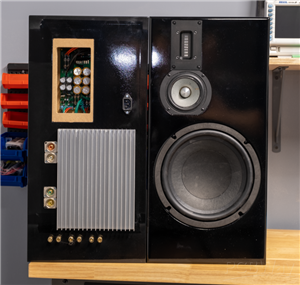
Initially I planned to build two speaker enclosures wired for tri-amping and a separate amplifier. But then decided to try and fit the amp inside the enclosure. It required using SMT components to build extremely small 6-channel amplifier with 4-way crossover network and speaker protection circuit. Let’s start with the amplifier topology.
Amplifier design
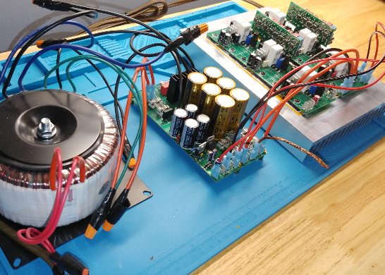
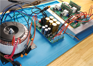
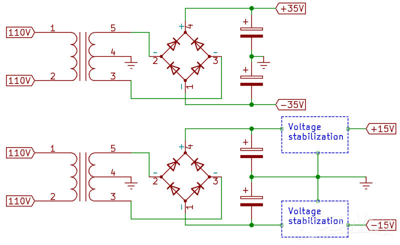
The power supply is linear. A toroidal transformer has two center tapped secondary windings: 300VA 25V-0-25V and 50VA 15V-0-15V. While this configuration isn’t readily available, you can special order it from multiple online stores or use two separate transformers. The secondaries are fused, just as both outputs. Only the low voltage supply requires stabilization. Both circuits are on the same PCB.
The crossover network is based on 4-th order Linkwitz–Riley topology. It provides 24db/octave roll-of with excellent phase-coherency, resulting in flat summed output at crossover frequency. A bandwidth definition filter removes all the subsonic signals and protects the loudspeakers. It consists of 3-rd order Butterworth highpass with 20Hz cutoff and 2-nd order Butterworth lowpass at 50kHz. The high frequency stage has 6dB gain to make signal less vulnerable to circuit noise. A cascaded 1st-order allpass filter provides a time delay to compensate for the difference in distance between tweeter’s and mid-range speaker’s acoustic centers and listener’s ear. Each output has a voltage divider, which allows to equalize the levels to each speaker’s sensitivity.
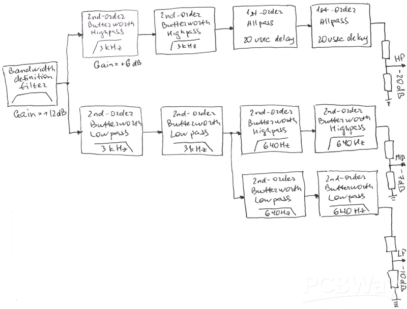
In order to extend the bass all the way to the floor, the provision is made on the PCB for two bass signal outputs. One is just a sum of low inputs. The other one is passed through two intergrators to provide a 12db/octave slope for an equlised sub-woofer design.

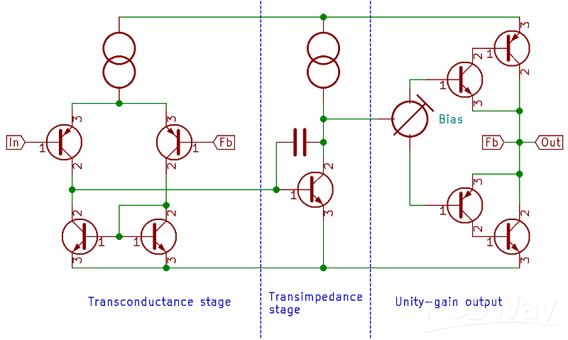
The power amplifier is a conventional 3-stage class-AB. A long-tailed pair input stage converts differential voltage into output current signal. The second stage provides about 27dB of voltage gain. And the output is configured as a unity-gain complementary-feedback pair for better thermal stability and linearity. Since there will be no capacitor between the amplifier output and the loudspeaker, additional protection is required. Should DC develop on the output, it will destroy the loudspeakers (tweeter almost instantly). To prevent it the amplifier output stage is equipped with MOSFET relays that cut-off output in a matter of milliseconds (the actual delay depends on the lowest operating frequency and is individually configured for each loudspeaker).
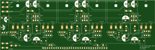
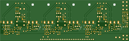
When you design amplifier layout it is very important to separate all signal tracks from power tracks. My first prototype was based on Self's design with all 6 amps placed on one PCB. And while the circuit turned out to be extremely precise (THD < 0.002%) it was also very unstable because I didn't separate high and low voltage circuits well enough. So I ended up simplifying the design to sacrifice some precision for stability. In order to fit 6 amplifiers and two 4-channel crossover networks into such a small form factor I had to go with SMT PCB design. I split the amp into 5 separate PCBs to keep routing simple and keep signal and power circuitry separate.
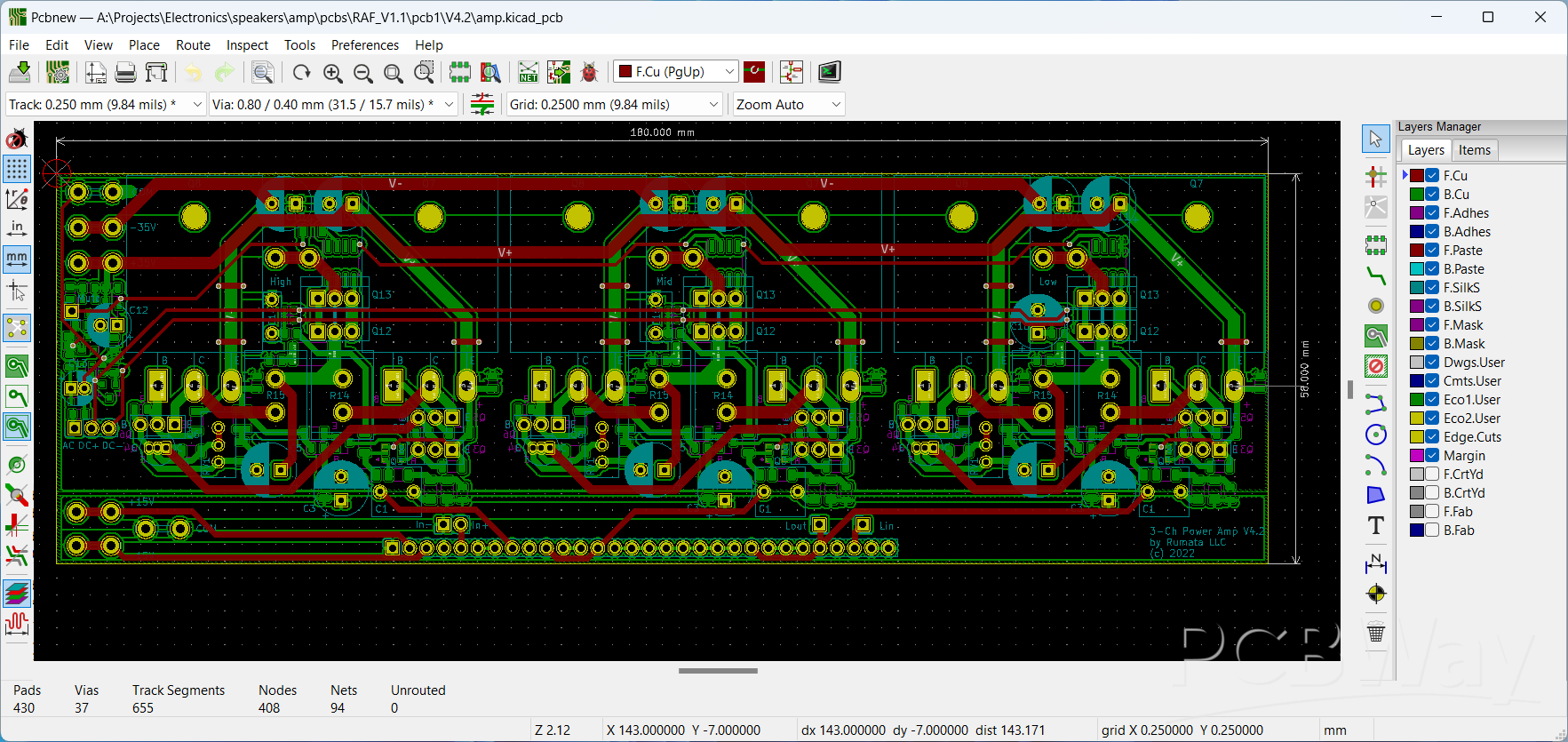
The design proved to be exceptionally quite and stable, and is capable of producing 60W into 8Ohm load from 35V power supply.
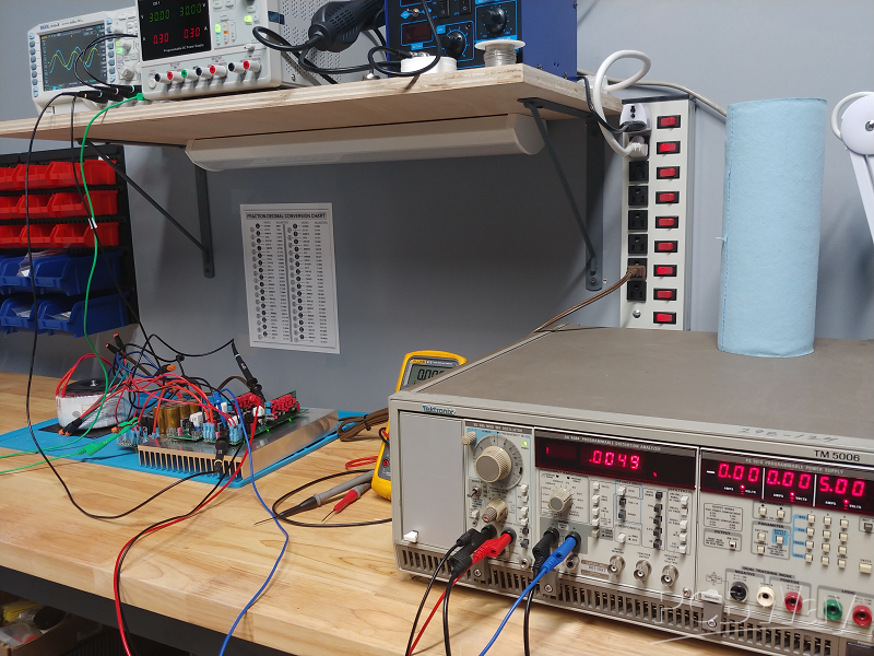
The final tests showed average THD+N = 0.02% at 60W. Low final bias current let's the amplifier run very cool. With my 0.4°C/W heatsink the idle temperature is about 40°C.
The rest of the project, including the enclosure design and assembly is described on my website.
4-way active class-AB audio amplifier
Project images are for reference only. Actual production is based on the manufacturing files on the project page.
Please review the designer's notes (e.g., PCB thickness) and select the appropriate options.
PCBWay is not responsible
for issues caused by unsuitable parameter selections.
For more important ordering information, please refer to
Read More


Raspberry Pi 5 7 Inch Touch Screen IPS 1024x600 HD LCD HDMI-compatible Display for RPI 4B 3B+ OPI 5 AIDA64 PC Secondary Screen(Without Speaker)
BUY NOW


- Comments(3)
- Likes(1)
More by Viktor Gunnerson
-
Programmable Mist Maker - XIAO / QT PY Extension
1184 2 1 -
RadioHAT - Raspberry Pi radio development platform
989 0 2 -
-
-
-
-
ARPS-2 – Arduino-Compatible Robot Project Shield for Arduino UNO
3403 0 6 -
A Compact Charging Breakout Board For Waveshare ESP32-C3
4027 3 8 -
AI-driven LoRa & LLM-enabled Kiosk & Food Delivery System
4422 2 2


