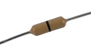
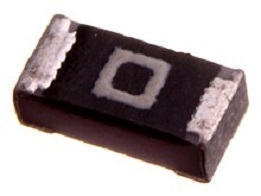
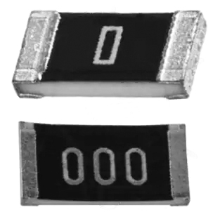
A zero-ohm resistor, also known as a jumper resistor, is a specialized resistor with a nominal resistance value of zero ohms. It is commonly used in PCB design and other applications as an idealized component. Despite being labeled as 'zero ohms,' the actual resistance value of a zero-ohm resistor is not exactly zero, but very close to it. There are two common packaging forms for zero-ohm resistors: axial lead zero-ohm resistors and surface-mount zero-ohm resistors.
Debugging and Compatibility
When hardware engineers design PCB boards, it's important to consider compatibility issues. For example, a certain pin of a chip might have two functions: driving a buzzer or driving an LED. However, these two functions cannot work simultaneously. In order to enable the selection of which module to drive on the same circuit board, a zero-ohm resistor can be added to the circuits connecting the buzzer and the LED. By soldering the zero-ohm resistor on either the buzzer's path or the LED's path, engineers can choose to drive either the buzzer or the LED.
As shown in the diagram below, signal usage can be selected, and the corresponding component can be soldered, and leave the unused one empty.
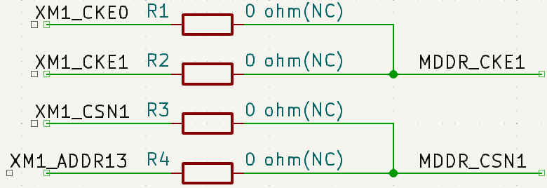
During configuration, especially for embedded systems, different boot sources can be chosen through on-board configurations when selecting the boot source signal. At this point, zero-ohm resistors are used.
Used as Jumpers
To reduce wiring complexity, enhance aesthetics, and simplify installation, while avoiding high-frequency interference caused by jump wires.
Bridging circuits during wiring
During the PCB layout and routing phase, there are instances where certain connections cannot be established easily, especially on small boards with numerous connections. In such cases, if a connection requires a lengthy detour to establish, a zero-ohm resistor can be used to bridge the previous traces. This doesn't add extra layers and helps reduce the production cost of the PCB.
Reserved for debugging
When circuit parameters cannot be ascertained during parameter matching and practical testing requires removing a resistor or trying different resistance values to achieve an optimal solution, a zero-ohm resistor is typically employed. The zero-ohm resistor is used as a placeholder until the specific parameter values are determined during actual testing, after which it's replaced with actual components of the precise values.
For instance, when there are two different supply voltage options, 5V and 10V, but uncertainty exists regarding whether the different power supply voltages would affect the entire circuit in an unknown way, a zero-ohm resistor is often used to connect them. This allows selecting the power supply connection during circuit debugging.
Measuring circuit power consumption
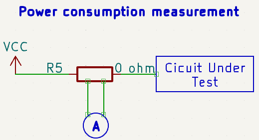
When unsure about the power consumption of a chip or an entire circuit, a zero-ohm resistor can be placed in series with the power supply terminal. After the prototype board is completed, the zero-ohm resistor can be removed, and the two solder points can be directly measured using a multimeter. This measurement helps determine the actual working current, aiding in the calculation of chip or overall circuit power consumption. If you want to measure the current consumption of a specific circuit section, you can attach a zero-ohm resistor and a current meter to facilitate current measurement, which is useful for measuring high currents.
As shown in the diagram below, a zero-ohm resistor is placed between the power supply terminal and the circuit being measured.
Acting as Capacitors or Inductors in High-Frequency Signals
Under high-frequency signals, a zero-ohm resistor, when matched with the external circuit characteristics, can function as a small capacitor or inductor. This can effectively address EMC issues, such as between ground connections or between power supply and chip pins.
Serving as Fuses for Overcurrent Protection
Due to the high fusing current of traces on a PCB, it's challenging for them to fuse during short circuits or overcurrent faults. This might lead to more significant accidents. However, the current-carrying capacity of a zero-ohm resistor is relatively weak, and it would melt first during overcurrent conditions. This action can disconnect the circuit, preventing more substantial accidents from occurring.
Single-Point Grounding for Analog and Digital Grounds
During circuit design, particularly in mixed circuits involving digital and analog components, it's often required to have separate grounds with a single-point connection. A zero-ohm resistor can be employed to connect these two grounds instead of directly joining them. This approach divides the ground lines into two networks, which proves beneficial during processes like large-scale copper pouring, preventing the accumulation of charge due to "floating ground" and static electricity.
In similar scenarios, the following methods might also be used to address this issue: 1) using ferrite beads; 2) using capacitors; 3) using inductors; 4) using zero-ohm resistors.
Used in Current Loop for Bypassing
When a ground plane is split, leading to the interruption of the shortest return path for a signal, the signal path has to take a detour, resulting in a significant loop area. This can amplify the influence of electric and magnetic fields, making it susceptible to interference or causing interference. Placing a zero-ohm resistor across the split area provides a shorter return path, reducing interference.
As shown in the diagram below, when two signals are communicating and situated on different ground planes, adding a zero-ohm resistor between these two signals forces the signals to take the shortest path.

Configuration Circuit
This function is similar to jumpers or DIP switches, but it's soldered in place to prevent casual modification by regular users. By installing resistors in different positions, the circuit's functionality or address settings can be altered.
Noise Suppression
Due to the characteristics of a 0-ohm resistor, it can effectively suppress loop currents, thereby attenuating noise. In reality, a 0-ohm resistor doesn't truly have zero impedance; only superconductors can achieve true zero impedance. Therefore, a 0-ohm resistor actually provides attenuation across all frequency bands.
Certainly, there are differences. As evident from the functions I mentioned earlier, the capabilities of a zero-ohm resistor are quite diverse. Furthermore, in some cases, the roles of a zero-ohm resistor and a wire are equivalent. For instance, during circuit bridging, zero-ohm resistors are used instead of wires because in the manufacturing process, surface mount technology (SMT) is employed, and SMT machines can recognize zero-ohm resistors while identifying wires can be challenging. Hence, for production efficiency and convenience, zero-ohm resistors are often chosen.
Yes, there is a distinction. For instance, when the accuracy of a zero-ohm resistor is specified as ±1% or ±5%, it comes in various package sizes such as 0603, 0805, 1206, 1210, 1812, and more. Different accuracies lead to varying dimensions and forms, as depicted in the diagram below.
In circuit design, zero-ohm resistors are often used, and the selection of the resistor's rated power is based on the circuit current. The actual resistance value of a typical zero-ohm resistor is around 50 milliohms with a deviation of approximately ±5%. Based on the rated power, you can calculate the rated current for the zero-ohm resistor.
For various package sizes, the calculation of the rated current is as follows:
0402 1/16W: 1/16 = I * I * 0.05, which gives I = 1.118A
0603 1/8W: 1/8 = I * I * 0.05, which gives I = 1.58A
0805 1/4W: 1/4 = I * I * 0.05, which gives I = 2.236A
However, the specific current-carrying capacity of a zero-ohm resistor for each package size also depends on the resistor's heat dissipation on the PCB.


