I like to test all of the vintage computers that I restore as thoroughly as possible, because thorough testing is necessary to verify correct operation - electronic devices are complex systems with lots of functionality and components, so just because something looks like it works (i.e. it boots), that doesn't necessarily mean that it works properly.
However, this can often be both difficult to do (due to requiring proprietary or obsolete hardware or software) and difficult to document/prove for posterity or to a potential buyer (usually through pictures and videos).
As such, I'm always on the lookout for methods of making this process easier and more effective, for all of the systems that I work on. For a lot of mainstream kit (such as the Commodore 64), diagnostic hardware and software is quite readily available to buy - however, this is not the case for all machines, so often it's necessary to make your own.
This was the case for my Commodore Amiga computers (i.e. A500, A600, A1200, etc). You can do a lot of manual testing on Amigas using basic peripherals - however, specialist hardware and software can be extremely useful for thorough testing.
Testing Commodore Amiga computers

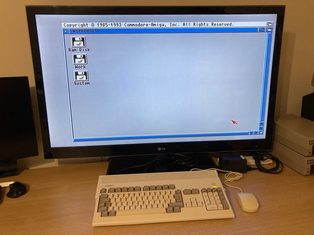
Commodore Amiga 1200 startup screen.
Manual testing can be performed with basic peripherals:
Automated testing can be performed using Keir Fraser's excellent Amiga Test Kit software, which is available to download or to buy on disk:
The only Amiga Test Kit tests that require dedicated diagnostic hardware are the serial and parallel port tests, however loopback adaptors were not available to buy at the time, so I set about making some of my own.
 RGB video testing
 Composite video testing
 PCMCIA testing
 IDE testing
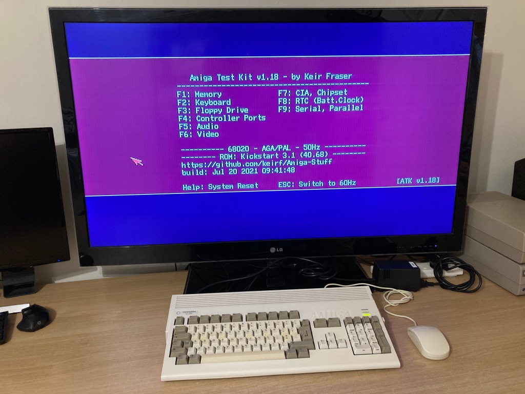 Amiga Test Kit main screen
 Amiga Test Kit RAM test screen
 Chip & fast RAM soak testing
 Keyboard testing
 Amiga Test Kit video test screen
 Video testing (a)
 Video testing (b)
 Video testing (c)
 Amiga Test Kit FDD test screen
 Internal FDD read tests
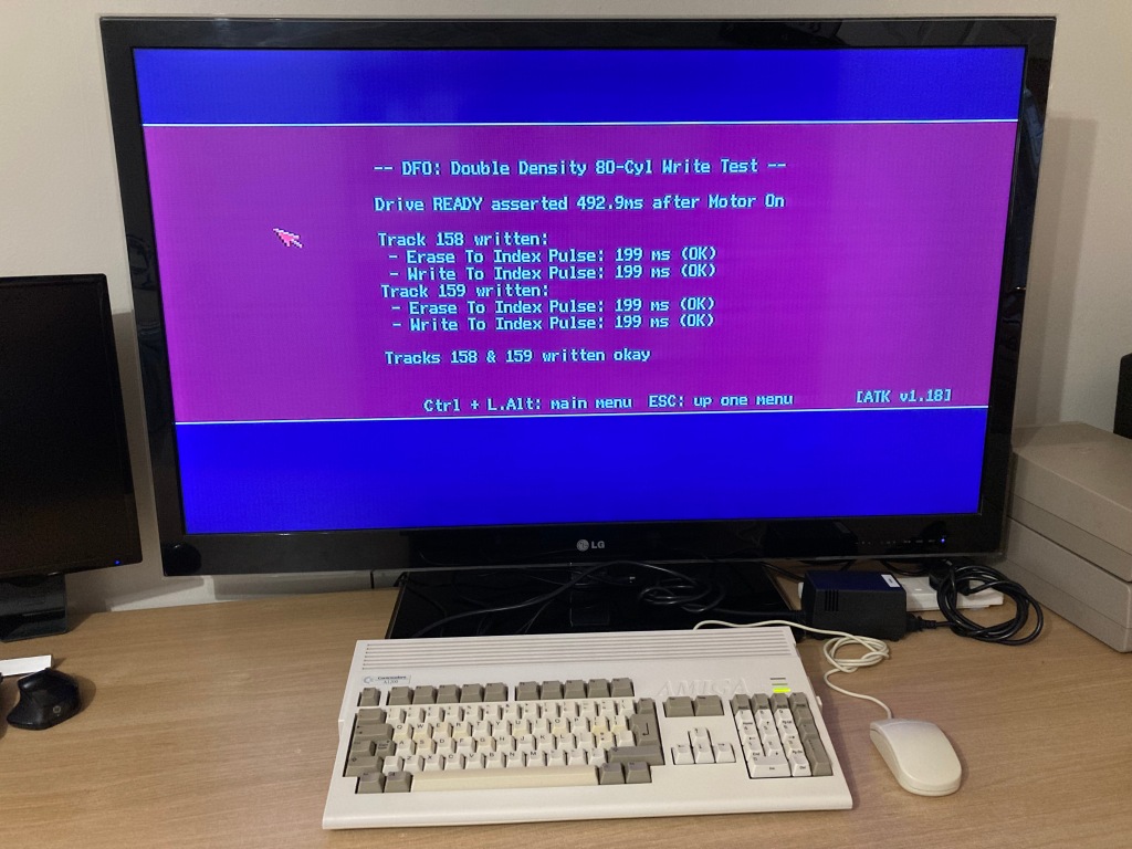 Internal FDD write tests
 External FDD read tests
 External FDD write tests
 Mouse & joystick tests
 Amiga Test Kit chipset screen
 CIA timer tests
 RTC testing
 Amiga Test Kit port screen
 Serial port testing
 Parallel port testing
What is a loopback adaptor?
A "loopback test" is a simple concept: transmitted electrical signals are fed back to the sender, allowing the sender to validate its own output. In communications (i.e. parallel and serial modems), the output of the transceiver needs to be connected to its own input - if the device receives its own output signal back, this proves that it is functioning.
This usually requires a simple hardware loop to physically connect the transmitter channel to the receiver channel. This could be as simple as soldering some wires to the appropriate plug, however I wanted a more long-lasting solution.
The Amiga serial port
Classic Amiga computers all feature the same standard RS-232 serial port, which uses a DB-25 male connector (on the computer side), the pinout for which is below.


The serial loopback requires that the following pins be connected together:
It is also possible to wire in two LEDs, to show that the +/-12Vdc supply rails are present.

The Amiga parallel port
Classic Amiga computers (except for the Amiga 1000) all feature the same standard Centronics parallel port, which uses a DB-25 female connector (on the computer side), the pinout for which is below. The A1000 uses a male DB-25 connector with a different pinout which makes it non-compatible, so it is not covered in this article.


The parallel loopback requires that the following pins be connected together:
It is also possible to wire in an LED, to show that the +5Vdc supply rail is present.

Building a set of loopback adaptors
At the time, no UK sellers sold Amiga serial and parallel loopback adaptors, so I had to make my own.
There are quite a few examples of people on the web making their own loopback adaptors - one even added a set of voltmeters built into the plugs, very nice!
As discussed earlier, it would be possible to just solder some wires onto two DB-25 connectors and call it a day, but I managed to find a set of open-source PCB designs for the serial loopback a href="https://www.pcbway.com/project/shareproject/AMIGA_TEST_KIT_PARALLEL_PORT_DONGLE.html" target="_blank">parallel loopback adapters, available on the PCBWay Shared Projects page. I decided to order a set of these PCBs (5 each, 10 total) through PCBWay because of how easy it is to order their shared project PCBs, and I had a very good experience overall.
These PCBs mount strongly to the DB-25 connectors as they sit between the connector pins and have large solder pads - they also have locations for a set of LEDs to show the presence of the +5Vdc, +12Vdc, and -12Vdc power rails.
Aside from the PCBs, a handful of components are required - per set, this includes:
1 x DB-25 male connector.
2 x DB-25 connector shrouds (optional).
3 x 5mm LEDs (optional) - I chose red for +5V, yellow for -12V, and green for +12V.
3 x 1/4W through-hole resistors for LED current-limiting (optional) - I chose 1KΩ for the +5V LED and 3.3KΩ for the +12V & -12V LEDs, as these gave a comfortable brightness.
I assembled a set of boards to test out, and they worked as expected.


Assembled loopback PCBs.
I also put together a set of cases, by drilling holes in the shrouds for the LEDs.


Assembled loopback dongles.
With the cases installed, the brightness of the LEDs seems to be just right.

LED brightness can be adjusted by changing the values of the current limiting resistors.
The results of testing using the loopback adaptors is shown below. Success!


Amiga 500 serial & parallel port testing with custom loopback dongles.
Review of PCBWay
I'm quite new to ordering custom PCBs (as a hobbyist, at least), so I thought I'd write a quick review of PCBWay to help out other new starters. These were the first PCBs that I've ordered for myself, and I'll definitely be buying more in the near future - I'd eventually even like to work my way up to developing my own circuit designs and layouts.
The minimum order quantity for these small PCBs was 5 each (10 total), at $5.00 per set ($10.00 total) - as a new user referred by a colleague of mine, I was given a $5.00 discount voucher, so the 10 PCBs came to only $5.00 in total (bargain!). You can claim your $5.00 new user voucher here, if you so wish.
When you add a design (or designs) to your online shopping cart, they will go through a short review process by your assigned sales rep. In my case, this took less than an hour.
Once you've placed your order, you are taken to a detailed order manufacturing screen, where you can track the process through each exact manufacturing step. I chose a 24-hour build time for this project, which was standard at no extra cost, and my boards were shipped the next working day.
Shipping via DHL (2-4 working days) between China and the UK cost around £20.00 for this order, and the parts arrived safely and extremely quickly. There are cheaper shipping options available (i.e. China Post), but these will take significantly longer to arrive.
For this order, I wasn't subject to any import charges, but this may apply to orders of greater value - these are the responsibility of the buyer, and will be paid following delivery.
My order was well packed, and the PCBs are of a very good quality, and work exactly as intended! PCBWay's communication and service throughout the process was also very good, and I'm very pleased with my experience overall.
The PCBWay Shared Projects page is extremely useful for quick prototyping, or for those like myself who don't currently have any of their own designs. Its integration with the ordering process is seamless, so it's very easy for hobbyists to get boards made. Shared project authors also get paid for their work when you buy.
There are lots of shared projects available for vintage computing enthusiasts in particular, and PCBWay seems to have a good standing in the community. If anyone has a project that they would like to share on the PCBWay page, they can do so here.
I hope this helps any PCB newbies like myself! If you have any questions, let me know and I'll try to help out if I can.
For more vintage computer related content, check out my website!
|
|
25 Way Male DB25 Connector |
x 1 | |
|
|
25 Way Female DB25 Connector |
x 1 | |
|
|
25 Way DB25 Connector Shroud |
x 2 | |
|
|
5mm LED |
x 3 | |
|
|
0.25W Through-Hole Resistor |
x 3 |


