Summary: We continue on this series of voltage amplification, for which we designed a coupling that, by the means of wave derivatives, converts DC to AC current, this article will have a continuation as more components are added to Magnos.
As seen in the previous article, we continue working with voltage amplification, this time, we talk about DC to AC wave generation.
Well, what can we say, this is going to get very technical, and math-wise, but don't worry if you're not familiar with the math expressions, we'll just wrap up and resume what each of the equations mean and how in the holy-powly we achieved full wave spectrum from DC to AC.
At the moment writing this article, I have a few oscillators, NE555, a protoboard and waiting for a very important piece which I will talk about later on this post, anyways, let's start.
This won't be an introduction to DC or AC, so we'll just jump directly to the content.
We have a source voltage of 180 volts, the previous article we wrote will help you understand how it's built. Right, so 180 volts, DC, but there is a small problem:
My microwave makes use of AC, not DC, what am I supposed to do in order to prepare my popcorn, or heat my pizza?
The answer is simple: Derivatives
Yep, that's right,
Fortunately, DC waves are not fully 100% clean, as they might have small peaks and valleys, in fact, no wave that I have seen is fully seamless, they have either curvature or peaks and valleys. For our bad luck, DC is made ouf of peaks and valles, thanks to math, we understand that there is no way we can transform a triangle completely into a circle, but that's a geometrical representation and assumption.
Like, the universe has circle and triangled-shaped things, it's just matter of thinking, well the wave it's like this

So pretty difficult to create a circle from that, isn't it? Physically, yes, magnetically, not so much.
Because the only difference between those triangle waves, and an AC wave is the distance they have, and the amount of oscillation that gets applied, if the frequency is bouncing back and forward, by the means of resistance, the triangle waves will kind of "round", so we will just need to transform those peaks and valleys into rounded shaped waves, and voila!
We have an AC wave. Simple right? Yeah, long story short, I'll share the schematic with you, and hopefully you notice that component that is missing.
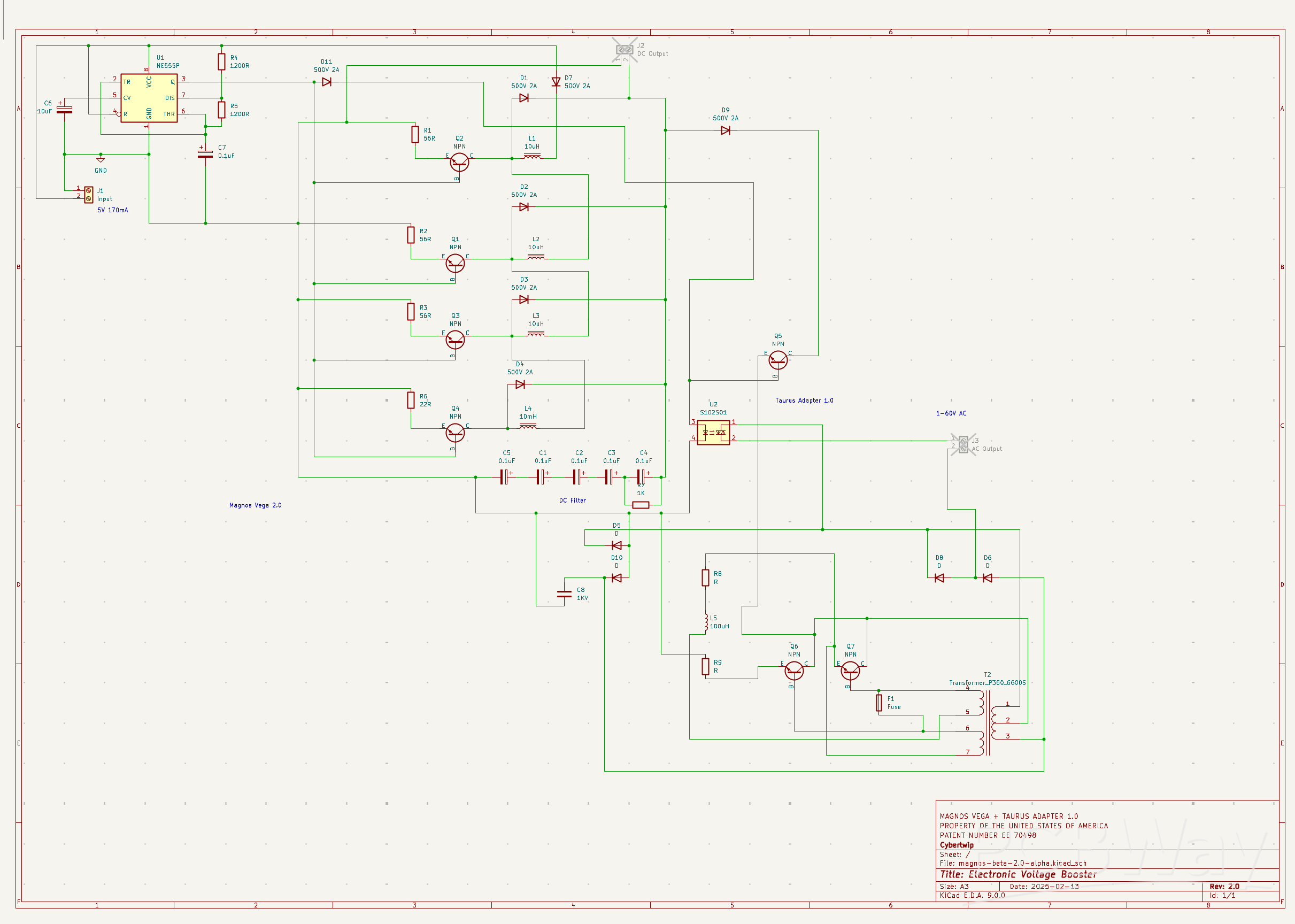
Between D9 and Q5 there is a missing digital potentiometer, as a theoretical example, and I'll follow up with the math after this chit-chat, if resistance values smooth waves and peaks, what if we just digitally adjust current? What will happen is that at a given frequency, the waves will stretch and contract not vertically, but horizontally, creating a very much effective AC wave.
Now, to the math:
Derivatives and Wave Transformation
Now, let’s explore the mathematics behind this transformation, focusing on derivatives and their role in shaping waves.
Step 1: Understanding the Triangular Wave
The NE555 generates a squared wave, after all the voltage amplification and rectification it becomes a triangle wave, which mathematically consists of linear segments. Imagine a wave that rises steadily to a peak, then drops back down, repeating periodically. If we express this wave as a function ( v(t) ) over time ( t ), its slope is constant between peaks and troughs. The derivative of this function, dv(t)dt, represents the rate of change of voltage. For a triangular wave, this derivative is a square wave, jumping between positive and negative constants (the slopes of the rising and falling segments) at the peaks and valleys.
For example, if the triangular wave has a peak voltage Vp
and a period ( T ):
Rising slope = 2VpT/2=4VpT
(over half the period),
Falling slope = −4VpT
.
The derivative dv(t)dt
flips between 4VpT
and −4VpT, a square wave. However, our goal isn’t a square wave—it’s a sine wave—so derivatives alone don’t get us there directly. Instead, they inform how circuit components respond to these changes.
Step 2: Smoothing with Filters
To transform the triangular wave into a sinusoidal AC wave, we need to "round off" its sharp corners. This is where resistors, capacitors, and inductors come in, forming filters that reshape the wave.
.
Here’s where the missing digital potentiometer between D9 and Q5 shines. By digitally adjusting ( R ), we alter the wave function. A lower ( R ) increases the wave function, allowing more harmonics through (less smoothing); a higher ( R ) decreases the wave function, enhancing smoothing. This adjustment stretches or contracts the wave horizontally—effectively tuning its frequency and shape in real-time. For our 60V AC output, this fine-tuning ensures the wave matches AC.
Conclusion: Math Meets Practicality
To wrap up, transforming DC to AC involves:
Generating a triangular wave from DC using an oscillator (NE555).
I'll continue on this series of voltage amplification once the digital potentiometers are available and within our workshop.
Without much more to add, we'll see you in our next article, here, on PCBWay.
This is Kai, Cybertwip's founder.
Thanks for reading.


