

|
|
IC L293D |
x 1 | |
|
|
IC REG. 5V AMS1117 |
x 1 | |
|
|
Transistor BC527 NPN |
x 2 | |
|
|
LED 3mm Red |
x 1 | |
|
|
LED 3mm Super Bright White |
x 2 | |
|
|
R 100 ohm 1/4W |
x 1 | |
|
|
R 1K ohm 1/4W |
x 2 | |
|
|
R 10K ohm 1/4W |
x 5 | |
|
|
C 100uF/16V |
x 1 | |
|
|
Active Buzzer 5V |
x 1 | |
|
|
Switch SPDT SS12d00 G3 |
x 1 | |
|
|
Screw Terminal Bock 5mm 2P |
x 3 | |
|
|
Male Header 1x40 Pin |
x 4 |
Wemos Motor Shield ESP8266
A Motor Shield Wemos ESP8266, it's good for build Wifi Robot Car controlled by Android phone.
You can find circuit diagram and source code on app ESP8266 WiFi Robot Car:
- Remote Control Mode:
- Obstacle Avoidance
- Object Follower
- Line Follower
Circuit Diagram:

Sketch Code Remote Control mode:
/******************* WiFi Robot Remote Control Mode ********************/ #include <ESP8266WiFi.h> #include <ESP8266WebServer.h> #include <ArduinoOTA.h> // connections for drive Motors int PWM_A = D1; int PWM_B = D2; int DIR_A = D3; int DIR_B = D4; const int buzPin = D5; // set digital pin D5 as buzzer pin (use active buzzer) const int ledPin = D8; // set digital pin D8 as LED pin (use super bright LED) const int wifiLedPin = D0; // set digital pin D0 as indication, the LED turn on if NodeMCU connected to WiFi as STA mode String command; // String to store app command state. int SPEED = 1023; // 330 - 1023. int speed_Coeff = 3; ESP8266WebServer server(80); // Create a webserver object that listens for HTTP request on port 80 unsigned long previousMillis = 0; String sta_ssid = "$your_ssid_maximum_32_characters"; // set Wifi networks you want to connect to String sta_password = "$your_pswd_maximum_32_characters"; // set password for Wifi networks void setup(){ Serial.begin(115200); // set up Serial library at 115200 bps Serial.println(); Serial.println("*WiFi Robot Remote Control Mode*"); Serial.println("--------------------------------------"); pinMode(buzPin, OUTPUT); // sets the buzzer pin as an Output pinMode(ledPin, OUTPUT); // sets the LED pin as an Output pinMode(wifiLedPin, OUTPUT); // sets the Wifi LED pin as an Output digitalWrite(buzPin, LOW); digitalWrite(ledPin, LOW); digitalWrite(wifiLedPin, HIGH); // Set all the motor control pins to outputs pinMode(PWM_A, OUTPUT); pinMode(PWM_B, OUTPUT); pinMode(DIR_A, OUTPUT); pinMode(DIR_B, OUTPUT); // Turn off motors - Initial state digitalWrite(DIR_A, LOW); digitalWrite(DIR_B, LOW); analogWrite(PWM_A, 0); analogWrite(PWM_B, 0); // set NodeMCU Wifi hostname based on chip mac address String chip_id = String(ESP.getChipId(), HEX); int i = chip_id.length()-4; chip_id = chip_id.substring(i); chip_id = "wificar-" + chip_id; String hostname(chip_id); Serial.println(); Serial.println("Hostname: "+hostname); // first, set NodeMCU as STA mode to connect with a Wifi network WiFi.mode(WIFI_STA); WiFi.begin(sta_ssid.c_str(), sta_password.c_str()); Serial.println(""); Serial.print("Connecting to: "); Serial.println(sta_ssid); Serial.print("Password: "); Serial.println(sta_password); // try to connect with Wifi network about 10 seconds unsigned long currentMillis = millis(); previousMillis = currentMillis; while (WiFi.status() != WL_CONNECTED && currentMillis - previousMillis <= 10000) { delay(500); Serial.print("."); currentMillis = millis(); } // if failed to connect with Wifi network set NodeMCU as AP mode if (WiFi.status() == WL_CONNECTED) { Serial.println(""); Serial.println("*WiFi-STA-Mode*"); Serial.print("IP: "); Serial.println(WiFi.localIP()); digitalWrite(wifiLedPin, LOW); // Wifi LED on when connected to Wifi as STA mode delay(3000); } else { WiFi.mode(WIFI_AP); WiFi.softAP(hostname.c_str()); IPAddress myIP = WiFi.softAPIP(); Serial.println(""); Serial.println("WiFi failed connected to " + sta_ssid); Serial.println(""); Serial.println("*WiFi-AP-Mode*"); Serial.print("AP IP address: "); Serial.println(myIP); digitalWrite(wifiLedPin, HIGH); // Wifi LED off when status as AP mode delay(3000); } server.on ( "/", HTTP_handleRoot ); // call the 'handleRoot' function when a client requests URI "/" server.onNotFound ( HTTP_handleRoot ); // when a client requests an unknown URI (i.e. something other than "/"), call function "handleNotFound" server.begin(); // actually start the server ArduinoOTA.begin(); // enable to receive update/uploade firmware via Wifi OTA } void loop() { ArduinoOTA.handle(); // listen for update OTA request from clients server.handleClient(); // listen for HTTP requests from clients command = server.arg("State"); // check HTPP request, if has arguments "State" then saved the value if (command == "F") Forward(); // check string then call a function or set a value else if (command == "B") Backward(); else if (command == "R") TurnRight(); else if (command == "L") TurnLeft(); else if (command == "G") ForwardLeft(); else if (command == "H") BackwardLeft(); else if (command == "I") ForwardRight(); else if (command == "J") BackwardRight(); else if (command == "S") Stop(); else if (command == "V") BeepHorn(); else if (command == "W") TurnLightOn(); else if (command == "w") TurnLightOff(); else if (command == "0") SPEED = 330; else if (command == "1") SPEED = 400; else if (command == "2") SPEED = 470; else if (command == "3") SPEED = 540; else if (command == "4") SPEED = 610; else if (command == "5") SPEED = 680; else if (command == "6") SPEED = 750; else if (command == "7") SPEED = 820; else if (command == "8") SPEED = 890; else if (command == "9") SPEED = 960; else if (command == "q") SPEED = 1023; } // function prototypes for HTTP handlers void HTTP_handleRoot(void){ server.send ( 200, "text/html", "" ); // Send HTTP status 200 (Ok) and send some text to the browser/client if( server.hasArg("State") ){ Serial.println(server.arg("State")); } } void handleNotFound(){ server.send(404, "text/plain", "404: Not found"); // Send HTTP status 404 (Not Found) when there's no handler for the URI in the request } // function to move forward void Forward(){ digitalWrite(DIR_A, HIGH); digitalWrite(DIR_B, HIGH); analogWrite(PWM_A, SPEED); analogWrite(PWM_B, SPEED); } // function to move backward void Backward(){ digitalWrite(DIR_A, LOW); digitalWrite(DIR_B, LOW); analogWrite(PWM_A, SPEED); analogWrite(PWM_B, SPEED); } // function to turn right void TurnRight(){ digitalWrite(DIR_A, LOW); digitalWrite(DIR_B, HIGH); analogWrite(PWM_A, SPEED); analogWrite(PWM_B, SPEED); } // function to turn left void TurnLeft(){ digitalWrite(DIR_A, HIGH); digitalWrite(DIR_B, LOW); analogWrite(PWM_A, SPEED); analogWrite(PWM_B, SPEED); } // function to move forward left void ForwardLeft(){ digitalWrite(DIR_A, HIGH); digitalWrite(DIR_B, HIGH); analogWrite(PWM_A, SPEED); analogWrite(PWM_B, SPEED/speed_Coeff); } // function to move backward left void BackwardLeft(){ digitalWrite(DIR_A, LOW); digitalWrite(DIR_B, LOW); analogWrite(PWM_A, SPEED); analogWrite(PWM_B, SPEED/speed_Coeff); } // function to move forward right void ForwardRight(){ digitalWrite(DIR_A, HIGH); digitalWrite(DIR_B, HIGH); analogWrite(PWM_A, SPEED/speed_Coeff); analogWrite(PWM_B, SPEED); } // function to move backward left void BackwardRight(){ digitalWrite(DIR_A, LOW); digitalWrite(DIR_B, LOW); analogWrite(PWM_A, SPEED/speed_Coeff); analogWrite(PWM_B, SPEED); } // function to stop motors void Stop(){ digitalWrite(DIR_A, LOW); digitalWrite(DIR_B, LOW); analogWrite(PWM_A, 0); analogWrite(PWM_B, 0); } // function to beep a buzzer void BeepHorn(){ digitalWrite(buzPin, HIGH); delay(150); digitalWrite(buzPin, LOW); delay(80); } // function to turn on LED void TurnLightOn(){ digitalWrite(ledPin, HIGH); } // function to turn off LED void TurnLightOff(){ digitalWrite(ledPin, LOW); }
Wemos Motor Shield ESP8266
Project images are for reference only. Actual production is based on the manufacturing files on the project page.
Please review the designer's notes (e.g., PCB thickness) and select the appropriate options.
PCBWay is not responsible
for issues caused by unsuitable parameter selections.
For more important ordering information, please refer to
Read More









Raspberry Pi 5 7 Inch Touch Screen IPS 1024x600 HD LCD HDMI-compatible Display for RPI 4B 3B+ OPI 5 AIDA64 PC Secondary Screen(Without Speaker)
BUY NOW

- Comments(0)
- Likes(1)
More by Bluino Bluino
-
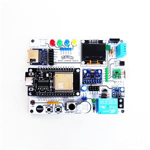 ESP32 IoT Starter Shield Version 3
Learn Basic IoT use ESP32 boards is very easy with ESP32 IoT Starter Kit board and following the 110...
ESP32 IoT Starter Shield Version 3
Learn Basic IoT use ESP32 boards is very easy with ESP32 IoT Starter Kit board and following the 110...
-
 ESP32-Cam Motor Driver Shield L293D
Android App: ESP32 Camera Wifi Robot CarTutorial Assembly:https://www.instructables.com/DIY-ESP32-Ca...
ESP32-Cam Motor Driver Shield L293D
Android App: ESP32 Camera Wifi Robot CarTutorial Assembly:https://www.instructables.com/DIY-ESP32-Ca...
-
 LED Blinking Robot Badge - Soldering Kit
This article is proudly sponsored by PCBWAY.PCBWAY make high quality prototyping PCBs for people all...
LED Blinking Robot Badge - Soldering Kit
This article is proudly sponsored by PCBWAY.PCBWAY make high quality prototyping PCBs for people all...
-
 3 Panel LED Dot Matrix MAX7219 for Common Anode Dot Matrix
Part List per Panel:1 x PCB LED Dot Matrix MAX7219 (PCBWay)1 x Led Dot Matrix 8x8 Common Anode1 x IC...
3 Panel LED Dot Matrix MAX7219 for Common Anode Dot Matrix
Part List per Panel:1 x PCB LED Dot Matrix MAX7219 (PCBWay)1 x Led Dot Matrix 8x8 Common Anode1 x IC...
-
 2 Panel LED Dot Matrix MAX7219 for Common Anode Dot Matrix
Part List per Panel:1 x PCB LED Dot Matrix MAX7219 (PCBWay)1 x Led Dot Matrix 8x8 Common Anode1 x IC...
2 Panel LED Dot Matrix MAX7219 for Common Anode Dot Matrix
Part List per Panel:1 x PCB LED Dot Matrix MAX7219 (PCBWay)1 x Led Dot Matrix 8x8 Common Anode1 x IC...
-
 IoT Basic Kit ESP8266 Wemos D1 Mini
Part List:1 x PCB IoT Basic Kit (PCBWay)1 x ESP8266 Wemos D1 Mini board1 x OLED I2C 128x641 x Humidi...
IoT Basic Kit ESP8266 Wemos D1 Mini
Part List:1 x PCB IoT Basic Kit (PCBWay)1 x ESP8266 Wemos D1 Mini board1 x OLED I2C 128x641 x Humidi...
-
 ESP32 IoT Basic Shield
Part List:1 x PCB ESP32 Basic Shield (PCBWay)1 x ESP32 DEV KIT V1 board1 x LED 5mm1 x LED 3mm1 x Act...
ESP32 IoT Basic Shield
Part List:1 x PCB ESP32 Basic Shield (PCBWay)1 x ESP32 DEV KIT V1 board1 x LED 5mm1 x LED 3mm1 x Act...
-
 Nodemcu Amica ESP8266 IoT Starter Shield
Learn Basic IoT use ESP8266 boards is very easy with Nodemcu IoT Starter Shield board and following ...
Nodemcu Amica ESP8266 IoT Starter Shield
Learn Basic IoT use ESP8266 boards is very easy with Nodemcu IoT Starter Shield board and following ...
-
 ESP32 Motor Shield 2WD
Control Robot Car 4WD Mecanum Wheel use app Android, install app here:https://play.google.com/store/...
ESP32 Motor Shield 2WD
Control Robot Car 4WD Mecanum Wheel use app Android, install app here:https://play.google.com/store/...
-
 ESP32 Motor Shield 4WD Mecanum Wheel
Control Robot Car 4WD Mecanum Wheel use app Android, install app here:https://play.google.com/store/...
ESP32 Motor Shield 4WD Mecanum Wheel
Control Robot Car 4WD Mecanum Wheel use app Android, install app here:https://play.google.com/store/...
-
 ESP32 IoT Starter Shield Ver 2.0
The difference from the previous version is that there is an additional slot for the HCSR04 ultrason...
ESP32 IoT Starter Shield Ver 2.0
The difference from the previous version is that there is an additional slot for the HCSR04 ultrason...
-
 nanBluino - DIY Arduino Nano USB Type-C
Overview"Arduino is an open-source electronics prototyping platform based on flexible, easy-to-use h...
nanBluino - DIY Arduino Nano USB Type-C
Overview"Arduino is an open-source electronics prototyping platform based on flexible, easy-to-use h...
-
 Drawbot Wifi ESP32 GRBL - Drawing Robot Plotter Pen
OverviewThe Drawbot is a drawing art robot that can draw. You will needs two stepper motors, a micro...
Drawbot Wifi ESP32 GRBL - Drawing Robot Plotter Pen
OverviewThe Drawbot is a drawing art robot that can draw. You will needs two stepper motors, a micro...
-
 Topeduino - DIY Arduino Uno USB Type-C use Solder Paste Stencil
Overview"Arduino is an open-source electronics prototyping platform based on flexible, easy-to-use h...
Topeduino - DIY Arduino Uno USB Type-C use Solder Paste Stencil
Overview"Arduino is an open-source electronics prototyping platform based on flexible, easy-to-use h...
-
 Eggbot Wifi ESP32 - Drawing Robot Plotter Pen
OverviewThe Eggbot is a drawing art robot that can draw on spherical or egg-shaped objects. You coul...
Eggbot Wifi ESP32 - Drawing Robot Plotter Pen
OverviewThe Eggbot is a drawing art robot that can draw on spherical or egg-shaped objects. You coul...
-
 ESP32 Balancing Robot Shield
Part list:1 x PCB ESP32 Balancing Robot Shield (PCBWay)1 x ESP32 DEVKIT V1 board2 x Stepper Motor Dr...
ESP32 Balancing Robot Shield
Part list:1 x PCB ESP32 Balancing Robot Shield (PCBWay)1 x ESP32 DEVKIT V1 board2 x Stepper Motor Dr...
-
 Pi Pico Starter Shield
Easy Way to Started learn Raspberry Pi Pico, based on official tutorial download Get Started Pi Pico...
Pi Pico Starter Shield
Easy Way to Started learn Raspberry Pi Pico, based on official tutorial download Get Started Pi Pico...
-
 ESP32 IoT Starter Kit
Learn Basic IoT use ESP32 boards is very easy with ESP32 IoT Starter Kit board and following the 110...
ESP32 IoT Starter Kit
Learn Basic IoT use ESP32 boards is very easy with ESP32 IoT Starter Kit board and following the 110...
-
Programmable Mist Maker - XIAO / QT PY Extension
2182 2 2 -
RadioHAT - Raspberry Pi radio development platform
1866 0 4 -
-
-
-
ARPS-2 – Arduino-Compatible Robot Project Shield for Arduino UNO
4060 0 6 -
A Compact Charging Breakout Board For Waveshare ESP32-C3
4812 3 8 -
AI-driven LoRa & LLM-enabled Kiosk & Food Delivery System
5621 2 2 -