


|
KiCADKicad
|
Steerable Microwave Beam
Microwave Beam Project
1. Project Overview
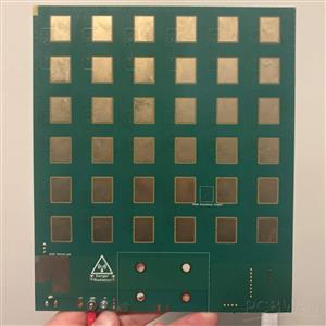
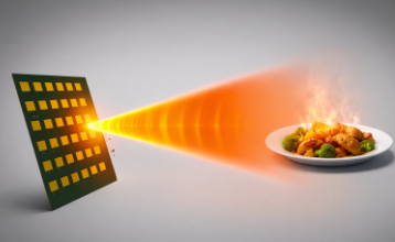
The system serves as a science demonstration platform that reveals the power and elegance of microwave circuit design, phased arrays, and high-frequency PCB engineering. The core concept is to electronically steer a beam of RF energy without any moving mechanical parts, using phase control across an array of patch antennas. This beam can then be used to transfer wireless power across a distance, light up LEDs, heat up food like a microwave, or boost WIFI signal by over 10,000x.
1.1. About me
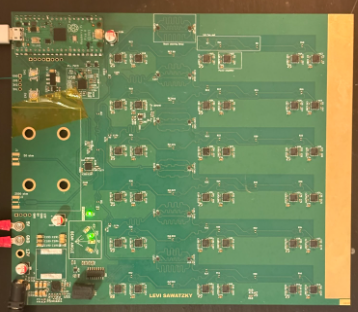
I am a junior electrical engineer from Canada, with a passion for building cool projects that push the boundaries of what's possible. I have a strong interest in electromagnetics, power electronics, and RF / microwave circuits. Some of my past projects include magnetic levitation, tesla coils, plasma generators, and radio transmitters (see them in my portfolio). I chose this project as a way to build my technical skills in areas that excite me, all while making a cool project that will show flashy, mind-bending results. This project pushes the limits of frequency that can be controlled with electronics. 5.8GHz
1.2. Key Results
A successful project will have the following results:
- Delivers powerful microwave energy across a distance
- heats up food, illuminates LEDs across a room
- 50-150 Watts of radiated energy
- Focuses energy beam as tightly as possible
- ~17° beam waist or 0.5m diameter at 2m
- Implementation of phased-array beamforming
- Steers over a range of 75° in 1 axis
- 4 programmable angles
Extra things to show off (stretch goals)
- Plasma generation inside noble gases
- Drone Defence / jamming
- Signal booster: boost effective wifi or drone SNR by ~1000x
- Recover radiated energy using a receiver antenna array (wireless drone charger?)
2. System Architecture
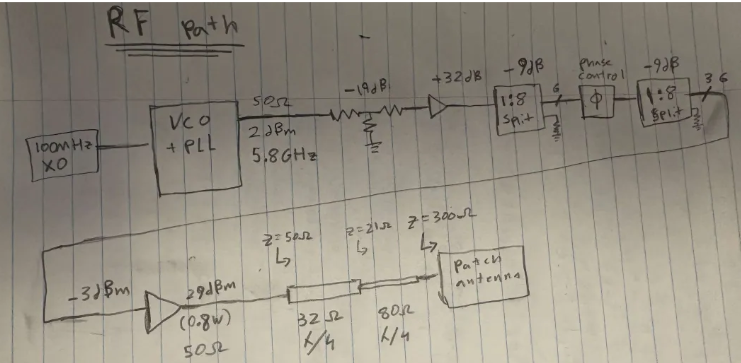
The beam is formed using a phased array of microstrip patch antennas. Each antenna element is driven with controlled phase offsets, allowing constructive interference in a desired direction and destructive interference elsewhere.
Core blocks include:
RF signal generation
Power amplification and attenuation
RF splitting network
Phase shifting network
Impedance matching and length tuning
Patch antenna design & array layout
3. Design Process
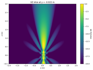
The design process involved lots of simulation. I used Ansys HFSS to optimize antenna shape, tuning, and impedance matching. I used python to simulate the array’s beamforming characteristics and beam steering.
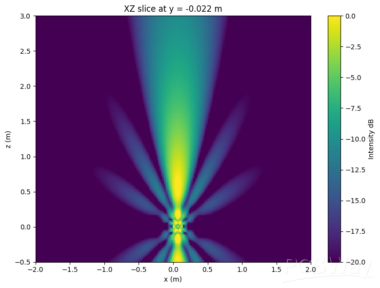
Simulating the beam from my array using python reveals a 3dB beam dispersion of 17 degrees.
3.1. Schematic design
Below I show some of the core blocks in the schematic design.
The full schematic can be seen in Kicad on my github: https://github.com/levisawatz/Microwave_beam_kicad
3.1.1 Power Distribution Network
To supply the power to the power hungry RF amplifiers, I’m using a DCDC switching regulator from TI. This chip can convert 12V to 5V at 40A. The onboard DCDC converter adds complexity as opposed to having an off board supply, however to ensure a clean 5V without losses from cables or connectors I decided this was the best option.
To power the rest of the circuit I used a separate 5V 1A DCDC power module. This allows the control circuits to not be affected by fluctuations caused by the power amplifiers, as well as adding a current limit so that short circuits in this rail don’t violently explode.
3.1.2 RF Generation
Creating a 5.8GHz signal is not trivial. I found a chip from Analog Devices: MAX2870ETJ+ that is a PLL + VCO frequency synthesizer. It is fed with a precision 100MHz signal and multiplies it to the desired frequency. The frequency and output power can be configured over SPI
3.1.3 Signal splitting and phase adjustment
By adjusting the phase of the signal at the antennas, the focus of the antenna array can shift. For example, delaying the left antennas more than the right ones causes the wavefront to steer to the left.
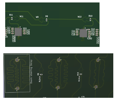
I use Wilkinson power dividers to split the RF signal into 6 for phase control, then 36 for final amplification. This type of signal splitter maintains matched impedance in the signal lines as well as providing isolation between the outputs.
Phase control is achieved using SP4T switches to select the appropriate delay path for the chosen beam steering angle. The chosen steering angles in degrees are: 45, 20, 0, -30. This provides 75 degrees of steerability, and 4 unique angles.
The SE5023L (or SE5004L-R) is used for the final amplification. Careful PCB layout is required to ensure proper thermal dissipation, impedance matching, and power supply decoupling.
4. PCB design
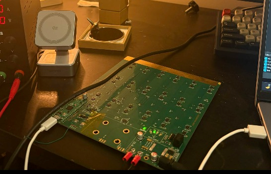
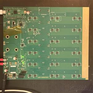
6 layers. 170x200 cm
Impedance controlled
Component count: 398 (34 unique)
PCB cost ~$370
Parts cost: ~$400
Assembly cost: ~$300
(source: PCBway)
4.0 Cost Justification
Cost is an important factor for me in my hobby projects, but it is also important that I build a project that I can be proud of. There were many decisions that I made that increased the cost considerably including upgrading from a 4x4 antenna array to 6x6, increasing the layer count from 4 to 6, Making use of impedance control, plugged vias for thermal management, and upgrading to ENIG finish for predictable thickness on the antennas. Assembly service would have saved me pain but it was not used because It pushed the project over budget.
4.1 Stackup
The following stackup was chosen using the 7628 dielectric material because of its affordability, low loss tangent, and its thickness - allowing for wider transmission lines, and less loss for high power signals. This also performed well in antenna simulations - giving the best bandwidth, which increases my chances of getting tuned antennas first try. This stackup was used to calculate trace width for transmission lines, and propagation delay for the length tuning.
4.2 Microstrip Impedance Matching
Quarter wavelength transformers are used to match the ~300 ohm patch antennas to the 50 ohm amplifiers. QWT was chosen over stub or lumped element matching due to its robustness: 20% inaccuracies in either the length or line impedance still lands with a manageable 10dB return loss. (this is now unnecessary with the new stackup allowing for antennas being 50 ohm)
Vias can cause impedance mismatch. The vias in my board are 1.6mm tall from the top to bottom layer. This is about 23 degrees of electrical length. Simulating my original via design (using Sierra via impedance calculator) revealed ~20 ohm vias resulting in a considerable impedance mismatch: increasing the VSWR above 2. Changing the via’s parameters (increasing the antipad size). Allowed me to tune the via impedance to 50 ohm: mitigating the mismatch
4.3. Thermal Considerations
The chosen microwave power amplifiers (SE5023L-R) are designed for telecommunication, and therefore have high linearity implying low efficiency. I estimate that using these amplifiers on a single tone at 1-4W output power, will result in efficiencies of ~25-35%. That means up to 7W of waste heat per amplifier: that’s 36W/cm^2. The DCDC converter produces 200W at 96% efficiency. That means up to 8W of heat generated.
This heat is mitigated through generous via stitching in the thermal pads, and large ground and power planes to spread out the heat quickly. The device will not be able to operate at max power for extended periods of time, but I hope to achieve bursts of up to 30 seconds.
5. Testing
The biggest risk in this project is the antenna tuning. I need to trust the PCB manufacturer’s (PCBway) material tolerance (dielectric constant, and loss tangent) as well as my accuracy in modeling them in Ansys. (also putting 36 antennas so close to each other likely affects tuning.)
Unfortunately, I do not own a VNA rated for 6GHz, and the cheapest trustable VNA I could buy us upwards of $1100 CAD
5.1. directional coupler
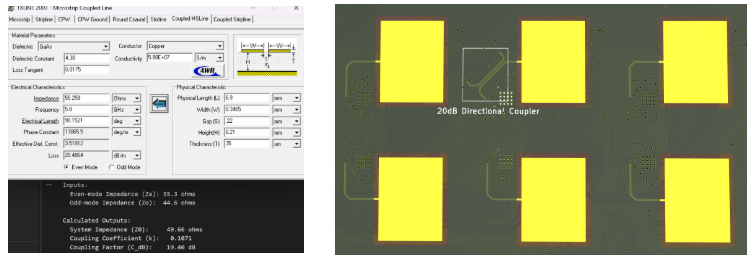
My solution to verifying antenna tuning is to use a directional coupler between the final stage power amp and the antenna. This microwave circuit can sniff the transmitted and reflected power independently which allows me to calculate VSWR.
5.2. Testing GUI
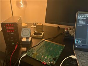
I created a custom GUI using Claude to configure RF output, and measure the power from the multiple stages. This helped streamline the testing considerably. Using the coupled output measurement, I can plot VSWR vs frequency just like a VNA.
6. Technical Challenges
This project was full of technical challenges from start to finish. Many were predicted but many were unexpected.
Sourcing RF components that operate reliably at the target microwave frequency (And which are within my budget)
Hand populating tiny QFN packages and hundreds of 0402 components
Creating firmware to interface with the complex VCO/PLL IC to generate a clean 5.8GHz signal
Thermal considerations under higher power levels
Most resistors and capacitors do not provide documentation of performance at high frequencies - especially as high as 5.8GHz. Below shows impedance vs frequency charts for resistors chosen for the T attenuator, and capacitors chosen for DC blockers. Murata’s “sim surf” website was very handy for choosing appropriate capacitors.
7. Problems and debugging
Oscillator wiring
Pin 1 of the crystal oscillator (X1) was pulled to ground disabling the oscillator: preventing any RF output. (I blame the confusing datasheet)
Floating the pin by scratching out the copper below pin 1 enables the oscillator solving the issue.
Massive signal losses
In my original design drawing and power calculations, I did not factor in signal losses. Initial power measurement tests showed 11.5 dB of loss between the two stages. The largest source of signal loss happens in the transmission lines. Referring to Sierra circuits, my transmission lines lose 0.28dB/cm at 5.8GHz. With a total length of 237 cm, I expect 7dB loss from the transmission lines alone.
Total expected losses
Transmission lines: -7dB (sierra)
RF switches (x2): -2.2dB (datasheet)
DC bypass caps: -.02dB (surfsim)
Amp tolerance: 0-2dB (datasheet)
Impedance mismatches: ?dB
Total expected: 9.2-11.2dB in losses. That's 90% of my signal lost!
Not a minor oversight, but I'm happy to have found an explanation for my measured losses.. Fortunately I have plenty of buffer in my available power to counteract the losses and I can still generate 40+ W at the output
DCDC Failure
The 5V 40A DCDC converter did not work - forcing me to use an external 5V supply. This was no big issue since I knew this design was risky, and had the backup plan and high current connection terminals ready.
Steerable Microwave Beam
Project images are for reference only. Actual production is based on the manufacturing files on the project page.
Please review the designer's notes (e.g., PCB thickness) and select the appropriate options.
PCBWay is not responsible
for issues caused by unsuitable parameter selections.
For more important ordering information, please refer to
Read More


Raspberry Pi 5 7 Inch Touch Screen IPS 1024x600 HD LCD HDMI-compatible Display for RPI 4B 3B+ OPI 5 AIDA64 PC Secondary Screen(Without Speaker)
BUY NOW


- Comments(2)
- Likes(1)
- 1 USER VOTES
- YOUR VOTE 0.00 0.00
-
10design
-
10usability
-
10creativity
-
10content
More by L D S
-
SmallOLED - Live PC Stats, Animated Clocks & Audio Visualizer
759 0 3 -
"Talking Multimeter": Arduino-Based Speech Add-on for Multimeters with SCPI Protocol
430 0 1 -
Programmable Mist Maker - XIAO / QT PY Extension
2886 2 3 -
RadioHAT - Raspberry Pi radio development platform
2465 0 4 -
-
-
-
ARPS-2 – Arduino-Compatible Robot Project Shield for Arduino UNO
4549 0 6