


|
|
LSM6DSR Breakout ModuleMofflab
|
x 8 | |
|
|
SuperMini NRF52840generic
|
x 8 | |
|
|
502030 Batterygeneric
|
x 8 | |
|
|
6x6x6 mm Push Buttongeneric
|
x 8 |

|
Autodesk Inventor |
|

|
KiCADKicad
|
SlimeVR Smol Trackers
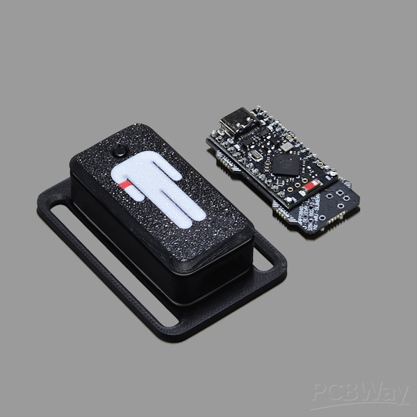
The design is centered around an inexpensive nRF52840 SuperMini clone paired with an LSM6DSV IMU mounted on a breakout board.
The full article is on my blog.
Set the PCB thickness to 1mm.
Required Tools
- Soldering Iron
- 3D Printer (Or 3D Printing Service)
- Sandpaper (400 grit)
- Superglue
- Multimeter to check electrical connections
- Pliers (for electronic projects)
- Windows PC (Linux can work too, check the proper documentation)
- A steady Hand
- Sanity
- Ideally a mini Hot plate too to simplify the sensor module soldering onto the PCB
Printing
The enclosure is designed to print easily on any FDM printer.
The only recommended, but not neccessary support is beneath the USB-C opening.
Everything else prints support-free.
All other parts can be printed without supports.
Soldering
- Begin by soldering the IMU breakout onto the carrier PCB. Either use a mini hotplate with solderpaste, or use a soldering iron to fill the castellated holes with solder to make a connection.
To make this succeed use the soldering iron at a flat angle to heat the castellated edge and apply solder to the pin. Try to force the solder down the hole to the pad.
Check the connection using a multimeter
Reheat if neccessary.
- Cut the supplied pin headers into groups of three or two pins.
- Place the SuperMini onto position and insert the trimmed headers from the MCU side of the PCB.
Solder the Headers on the IMU side of the PCB.
- Remove the plastic spacers from the headers.
- Solder the exposed header pins to the MCU.
- Trim the excess pin length on the MCU side down.
- Solder the push button onto the IMU side.
- Finally, solder the battery leads or connector on the MCU side.
**Warning:** Be careful not to short out the battery if soldering the leads directly! This includes cutting, stripping the wire and soldering!
Final Assembly
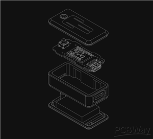
Once the electronics and enclosure are complete, the tracker can be assembled.
Slide the PCB into the enclosure.
The USB-C connector should align with the opening in the enclosure.
Carefully tuck the battery into its compartment.
Finally, press the rear cover into place until the clips engage.
The peg of the cover should align with the push button to transfer the forces.
Firmware and Configuration
The following steps were performed on Windows.
Linux should also work, although the exact process may differ slightly depending on your setup.
Prerequisites:
Before flashing the trackers, install the required software:
nRF Connect for Desktop to Flash the Firmware to the Dongle and Trackers.
SmolSlimeConfigurator To configure the Trackers after flashing if neccessary.
Dongle Firmware
Begin by plugging the HolyIOT USB dongle into your computer.
Open nRF Connect for Desktop and launch the Programmer application.
To enter DFU mode, hold the supplied magnet against the LED on the dongle.
If successful, the status LED will begin pulsing red.
The dongle should now appear inside the Programmer application.
Select it, choose the .hex firmware file, and flash it to the device.
Once flashing is complete, the dongle is ready for pairing with the trackers.
Tracker Firmware
Flashing the trackers is a simpler process.
Most SuperMini boards are shipped with a UF2 bootloader already installed.
After connecting the tracker to your computer using USB-C, it should appear as a removable USB drive.
Copy the provided .uf2 firmware file onto this drive.
The tracker will automatically reboot once flashing has completed.
After restarting, the tracker should automatically enter pairing mode and be recognized by the dongle.
Open the SlimeVR server software to see the tracker status and sensor values.
Finished Product
Once all trackers have been paired, the trackers will automatically appear in the overview, where they can be assigned to their respective body positions.
For the Final Step, the trackers need to be calibrated.
Simply lay them flat on the ground and press the button two times.
After a few seconds the tracker has calibrated, and it is ready for use.
SlimeVR Smol Trackers
Project images are for reference only. Actual production is based on the manufacturing files on the project page.
Please review the designer's notes (e.g., PCB thickness) and select the appropriate options.
PCBWay is not responsible
for issues caused by unsuitable parameter selections.
For more important ordering information, please refer to
Read More









Raspberry Pi 5 7 Inch Touch Screen IPS 1024x600 HD LCD HDMI-compatible Display for RPI 4B 3B+ OPI 5 AIDA64 PC Secondary Screen(Without Speaker)
BUY NOW


- Comments(2)
- Likes(0)
 More by Bevelgear
-
SmallOLED - Live PC Stats, Animated Clocks & Audio Visualizer
858 0 3 -
"Talking Multimeter": Arduino-Based Speech Add-on for Multimeters with SCPI Protocol
503 0 1 -
Programmable Mist Maker - XIAO / QT PY Extension
2971 2 3 -
RadioHAT - Raspberry Pi radio development platform
2517 0 4 -
-
-
-
ARPS-2 – Arduino-Compatible Robot Project Shield for Arduino UNO
4591 0 6


















