



|
KiCad 9.0 |
Segnapunti (Scorekeeper) - Up-Down counter module
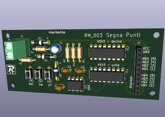
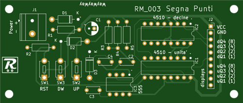
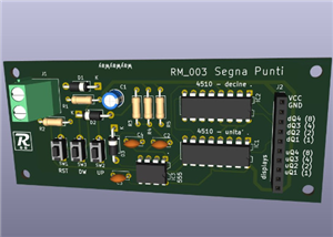
This PCB manages two CD4510 chips to count from 0 to 99 upward or downward, with three buttons: UP to increase the number by 1, DOWN to decrease the number by 1 and RESET to go back directly to 0.
The signals of the two chips and the power supply go out through a 10 pin strip where you can connect a module that manages the 7 segments displays. I have designed this module too, look at "2-digit led display module" (https://www.pcbway.com/project/shareproject/2_digit_led_display_module_7e0c38c6.html). Otherwise you can use the BCD format signals your way, for example with bigger 7 segments displays.
The 10 pins are arranged in this way:
VCC | GND | dD (8) | dC (4) | dB (2) | dA (1) | uD (8) | uC (4) | uB (2) | uA (1)
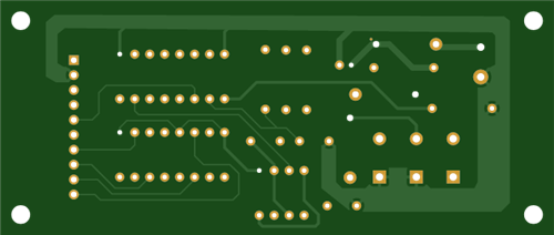
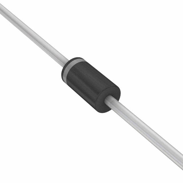
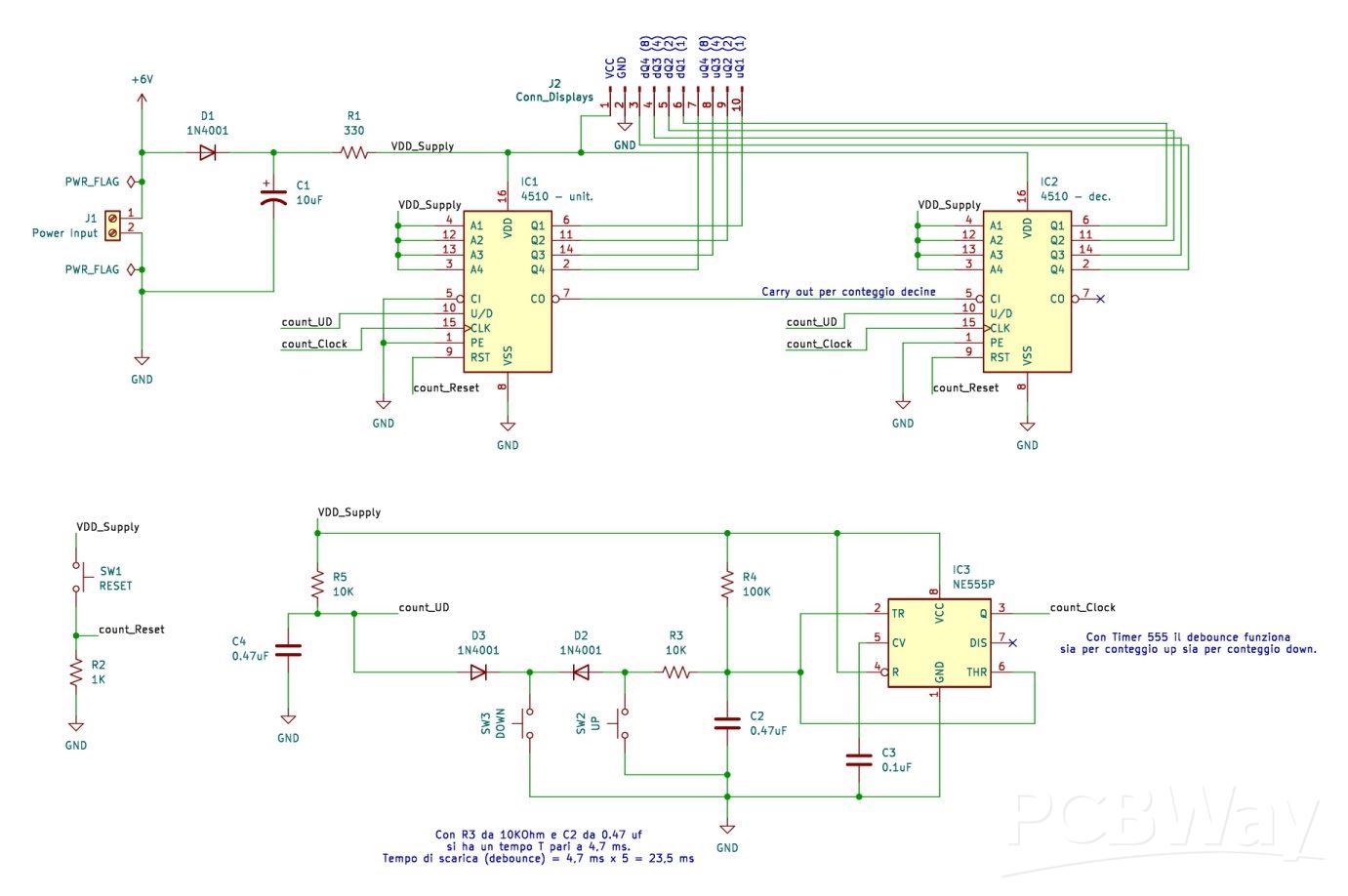
The peculiarity of this PCB is that it switches the UP\DOWN pin of the CD4510 chips with the same button that send the signal to count. This is posssible thanks to a group of diodes, resistors, capacitors and even a Timer 555 chip that manage the debouncing of the buttons too.
If you look at the image of the schema, you can see the switch signal as "count_UD" line and the count signal as "count_Clock" line going to both the CD4510 chips.
The same happens for the reset function, see "count_Reset" line, even if in this case the signal is managed only with a button and a pull-down resistor.
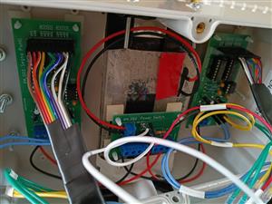
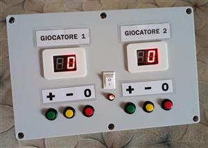
I wanted to create a box to keep the scores of two players.
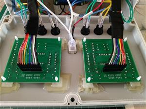
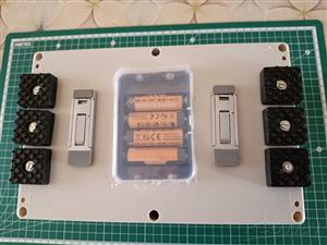
In the photos you can see as I used my "Power Switch" module (https://www.pcbway.com/project/shareproject/Power_Switch_module_ba904482.html) to power two "Segnapunti" modules connected to two "2-digit led display" modules to create this box.
I put on the front of the box the two led displays by fastening the "2-digit led display" modules on the rear of the cover along with the power led and the power switch that comes from the "Power Switch" module, below the displays there are the relative buttons for the counting wired to the "Segnapunti" modules sitting on bottom of the box. You can easily understand all the wires by looking at their different colours.
Red and black for the main supply are mandatory, then there is white for the power switch, again red and black for the power led, each counting buttons has its own color, then there are the 10-wire cables for the signals between each couple of PCBs ("2-digit led display" and "Segnapunti").
Segnapunti (Scorekeeper) - Up-Down counter module
Project images are for reference only. Actual production is based on the manufacturing files on the project page.
Please review the designer's notes (e.g., PCB thickness) and select the appropriate options.
PCBWay is not responsible
for issues caused by unsuitable parameter selections.
For more important ordering information, please refer to
Read More









Raspberry Pi 5 7 Inch Touch Screen IPS 1024x600 HD LCD HDMI-compatible Display for RPI 4B 3B+ OPI 5 AIDA64 PC Secondary Screen(Without Speaker)
BUY NOW


- Comments(2)
- Likes(0)
 More by Renato M.
-
 Segnapunti (Scorekeeper) - Up-Down counter module
This PCB manages two CD4510 chips to count from 0 to 99 upward or downward, with three buttons: UP t...
Segnapunti (Scorekeeper) - Up-Down counter module
This PCB manages two CD4510 chips to count from 0 to 99 upward or downward, with three buttons: UP t...
-
 2-digit led display module
This PCB has 2-digit 7-segment led to show numbers that changes from 0 to 99, like for example a cou...
2-digit led display module
This PCB has 2-digit 7-segment led to show numbers that changes from 0 to 99, like for example a cou...
-
 Power Switch module
A generic PCB that has power input, a switch to power on up to 4 external circuits and a led showing...
Power Switch module
A generic PCB that has power input, a switch to power on up to 4 external circuits and a led showing...
-
SmallOLED - Live PC Stats, Animated Clocks & Audio Visualizer
627 0 3 -
"Talking Multimeter": Arduino-Based Speech Add-on for Multimeters with SCPI Protocol
355 0 1 -
Programmable Mist Maker - XIAO / QT PY Extension
2794 2 3 -
RadioHAT - Raspberry Pi radio development platform
2397 0 4 -
-
-
-
ARPS-2 – Arduino-Compatible Robot Project Shield for Arduino UNO
4490 0 6


















