



|
KiCADKicad
|
|

|
BlenderBlender Inc.
|
|
|
|
ngscopeclientopen source
|
PYNQ-Z2 Mixed-Signal Oscilloscope | FPGA-Based Open Instrumentation & AI Integration
PYNQ-Z2 Mixed-Signal Oscilloscope
GitHub: https://github.com/Ross0907/pynq-z2-mixed-signal-oscilloscope
Overview
The PYNQ-Z2 Mixed-Signal Oscilloscope is a custom-developed FPGA-based instrumentation platform combining a dual-channel 16-bit oscilloscope, logic-analyzer connectivity, and an arbitrary waveform/function generator.
The project aims to develop an accessible, reconfigurable alternative to conventional closed instrumentation systems, bringing together analog circuit design, FPGA processing, high-speed PCB engineering, and software-defined measurement.
Beyond conventional waveform acquisition, the architecture is designed to support future integration with AI-assisted laboratory automation.
Hardware Architecture
The acquisition subsystem incorporates the AD9655 dual 16-bit ADC, ADA4817-2 high-speed amplifiers, ADA4927-2 fully differential driver, and TMUX1574 analog multiplexers.
Two acquisition configurations are provided:
DUAL: Simultaneous acquisition at 62.5 MSPS per channel.
FAST: Single selected-channel acquisition at 125 MSPS.
Each analog input incorporates protection, selectable attenuation, AC/DC coupling, amplification, and switchable anti-alias filtering.
An AD9102-based arbitrary waveform generator provides a separate signal-generation subsystem.
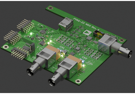
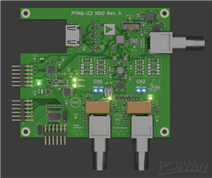
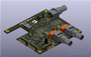
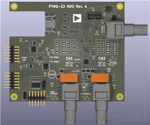
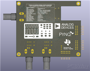
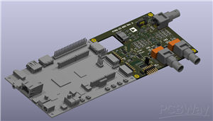
The custom four-layer PCB integrates analog front ends, dedicated clocking, power conversion, local regulation, FPGA interconnects, logic-analyzer connectivity, and three BNC connectors.
Design and Engineering Validation
The complete analog acquisition path was evaluated using Cadence PSpice, considering both channels, acquisition configurations, ADC loading, switching, filtering, and input coupling.
Pre-fabrication simulation results include:
ParameterResultFAST -3 dB bandwidth41.37–41.47 MHzDUAL -3 dB bandwidth22.05–22.07 MHzFAST Nyquist rejection41.74–42.22 dBDUAL Nyquist rejection36.19–36.28 dBAC coupling corner3.44–3.47 Hz
The engineering workflow additionally incorporates KiCad PCB design, post-layout extraction, signal-integrity analysis, and power-integrity verification.
These figures represent simulation results, not measurements from fabricated hardware.
Extending the Platform: AI-Assisted Instrumentation
A major future development direction is integration with ngscopeclient and the Model Context Protocol (MCP).
The proposed architecture connects the FPGA acquisition backend to ngscopeclient through a custom libscopehal-compatible instrument driver. An MCP server would subsequently expose structured instrument-control and measurement capabilities to compatible AI assistants.
This would enable natural-language interaction with physical measurement hardware, including:
Configuring acquisition, triggering, and waveform generation.
Capturing and analyzing analog and digital waveforms.
Performing automated frequency, amplitude, FFT, and noise measurements.
Decoding digital communication protocols.
Comparing acquired measurements against design specifications.
Assisting with circuit debugging and generating reproducible test reports.
The longer-term objective is to evolve the oscilloscope into an AI-accessible laboratory instrument capable of participating in automated experimental workflows.
The MCP/ngscopeclient integration is a proposed extension; it is not presented as an already validated implementation.
Project Vision
This project demonstrates how custom mixed-signal hardware, FPGA-based acquisition, open-source instrumentation software, and AI interfaces can be combined into a modular platform for electronics research, education, debugging, and future autonomous laboratory development.
Complete project development and engineering documentation are maintained on GitHub.
PYNQ-Z2 Mixed-Signal Oscilloscope | FPGA-Based Open Instrumentation & AI Integration
Project images are for reference only. Actual production is based on the manufacturing files on the project page.
Please review the designer's notes (e.g., PCB thickness) and select the appropriate options.
PCBWay is not responsible
for issues caused by unsuitable parameter selections.
For more important ordering information, please refer to
Read More









Raspberry Pi 5 7 Inch Touch Screen IPS 1024x600 HD LCD HDMI-compatible Display for RPI 4B 3B+ OPI 5 AIDA64 PC Secondary Screen(Without Speaker)
BUY NOW


- Comments(0)
- Likes(0)
 More by Engineer
-
SmallOLED - Live PC Stats, Animated Clocks & Audio Visualizer
619 0 3 -
"Talking Multimeter": Arduino-Based Speech Add-on for Multimeters with SCPI Protocol
351 0 1 -
Programmable Mist Maker - XIAO / QT PY Extension
2791 2 3 -
RadioHAT - Raspberry Pi radio development platform
2393 0 4 -
-
-
-
ARPS-2 – Arduino-Compatible Robot Project Shield for Arduino UNO
4487 0 6


















