


|
EagleAutodesk
|
|

|
arduino IDEArduino
|
PCBWay WiFi ESPBoard-01
Can you imagine controlling any device over the internet? Lamps, water pumps for irrigation, gate drive and many other things. All of this can easily be done for less than $5 if you use the ESPBoard-01 PCBWay Wifi.
This board combines several features that allow you to automate and control devices connected to the internet.
This project was developed with PCBWay, manufacturer of printed circuit boards. You can access this site, download all the electronic board files and get 10 free PCBWay units.
Read the full article and see the step by step to receive the electronic boards.
There are several solutions available on the market for controlling devices with internet. However, there is one big problem: you cannot modify the control code. This prevents you from creating your own ideas and creating something according to your or a client's need.
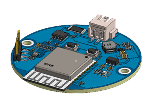
PCBWay WIFI ESPBoard-01 allows you to create any type of control logic over the internet. See its structure in Figure 1.

In this article you will learn:
- Develop a board for WiFi control,
- Understand the operation of a voltage regulator circuit,
- How to create a circuit with isolated source to activate a relay, and
- How to create a circuit to configure the ESP-01 for programming mode.
Next, we will present the complete circuit of the project and make the board files available for you to download.
Electronic Schematic of the ESPBoard-01 WiFi PCBWay Board
The electronics design is divided into 3 parts: power circuit, Wifi circuit, and relay drive circuit. Below is the complete schematic of the board's electronics design.

Now we will introduce the ESPBoard-01 PCBWay Wifi board power circuit.
Power Supply Circuit
The board's electronic circuit can be powered with an input voltage of 7V to 12V through the 2.1 mm Jack connector. At the jack connector input there is a 1N4001 diode, which is used to protect the circuit against polarity reversal of the power supply.
The circuit has two voltage regulators: AMS1117-5V and AMS1117-3V3. The AMS1117-5V is responsible for receiving the input voltage and providing a regulated output voltage of 5V.
In the figure below we have the region of the power supply circuit of the project.

This voltage will be used to drive the relay coil and the board energized LED indicator.
The LED circuit is shown below and it will be activated whenever the board is supplied with voltage.
The AMS1117-3V3 receives the supply voltage of 5V and provides a regulated output voltage of 3V3. This voltage is used to power the ESP-01.
The Wifi Control Circuit and Programming
This circuit is responsible for connecting and programming the ESP-01. See the electronic schematic in the figure below.

The circuit is formed by the ESP-01 connection pins, code transfer pins and the Flash and Reset buttons to put the ESP-01 in programming mode. See the circuit region in the figure below.

How does the code transfer process for ESP-01 work?
To do this, you must perform the following steps:
- Connect the USB-SERIAL FTDI232 converter to your computer and to the ICSP Pin Connections bar;
- Check that the LED is on. It is used to indicate that the card is powered;
- Select the COM port of your FTDI232 USB-SERIAL converter;
- Press and hold the FLASH button;
- Press and release the RESET button. After that, you will see the blue ESP LED to flash once.
Ready! Your ESP01 is configured to receive a new code. Now, carry out the process of transferring your code through the Arduino IDE.
After the transfer, your code will be recorded in the ESP01's memory and it will be ready to control your application.
Now, let's look at the relay triggering circuit.
Relay control circuit
Most circuits used to drive relays are not electrically insulated. During the activation of the coil, the relay generates electromagnetic noise and causes malfunctions in the problem.
To avoid this problem, we used a circuit with a PC817 optocoupler. See electronic schematic below.

As you can see, the IC PC817 isolates the ESP8266 drive circuit from the relay circuit. The phototransistor is driven by an optical signal, which comes from the photodiode.
The PC817 phototransistor is not capable of carrying current to drive the relay coil. For this we use a BC337 transistor (T1), which will be activated and will allow the activation of the relay coil, as this transistor has a collector current capacity of 800mA. See the figure below.

Another important point to note is the power supply to drive the relay coil. Note that there are two ways: use the circuit's own power supply or an external power supply through the JD-VCC jumper configuration. See the figure below.

The safest way is to use an external power supply, as this avoids interference from electromagnetic noise in the ESP-01 power supply.
Therefore, you must configure the JD-VCC pin to use an external power supply.
All electronic components of this project are presented in this bill of materials. Click on the link and download now!
Now you can download the files and earn 10 PCBWay electronic boards. Follow the step by step below.
- Download the Gerber File (PCB Project Manufacture) in this article;
- Acess this link, create your account and submit the Gerber File;
Ready! You'll receive 10 free PCB's in your house.
Conclusion
In the next articles we will present the result of manufacturing the electronic board and we will make a control application with the ESP-01.
Thanks to the PCBWay for support and produce and assembly PCBs with better quality.
PCBWay WiFi ESPBoard-01
*PCBWay community is a sharing platform. We are not responsible for any design issues and parameter issues (board thickness, surface finish, etc.) you choose.


Raspberry Pi 5 7 Inch Touch Screen IPS 1024x600 HD LCD HDMI-compatible Display for RPI 4B 3B+ OPI 5 AIDA64 PC Secondary Screen(Without Speaker)
BUY NOW


- Comments(1)
- Likes(2)
More by Silícios Lab silicioslab
-
 How to measure weight with Load Cell and HX711
IntroductionThe purpose of this project is to develop a printed circuit board (PCB) that allows weig...
How to measure weight with Load Cell and HX711
IntroductionThe purpose of this project is to develop a printed circuit board (PCB) that allows weig...
-
 Electronic Enclosure applied for electronic projects
IntroductionWhen designing electronics, the enclosure plays a crucial role that is often overlooked....
Electronic Enclosure applied for electronic projects
IntroductionWhen designing electronics, the enclosure plays a crucial role that is often overlooked....
-
 IoT Indoor system with ESP32 to monitor Temperature, Humidity, Pressure, and Air Quality
IntroductionAir quality, temperature, humidity and pressure are essential elements to ensure healthy...
IoT Indoor system with ESP32 to monitor Temperature, Humidity, Pressure, and Air Quality
IntroductionAir quality, temperature, humidity and pressure are essential elements to ensure healthy...
-
 WS2812B RGB LED Controller with ESP8266 via WiFi
IntroductionWS2812b addressable RGB LEDs are devices widely used in lighting projects. They are foun...
WS2812B RGB LED Controller with ESP8266 via WiFi
IntroductionWS2812b addressable RGB LEDs are devices widely used in lighting projects. They are foun...
-
 Electronic Board for Cutting Electrical Power to Devices and Machines
IntroductionAn energy saving system for cutting electrical energy in machines is a fundamental piece...
Electronic Board for Cutting Electrical Power to Devices and Machines
IntroductionAn energy saving system for cutting electrical energy in machines is a fundamental piece...
-
 PCB Board Home Automation with ESP8266
IntroductionThe incorporation of the ESP8266 module into home automation represents a significant ad...
PCB Board Home Automation with ESP8266
IntroductionThe incorporation of the ESP8266 module into home automation represents a significant ad...
-
 Dedicated Control Board for Mobile Robots with Wheels
IntroductionFor a long time we developed several prototypes and teaching kits of mobile robots and w...
Dedicated Control Board for Mobile Robots with Wheels
IntroductionFor a long time we developed several prototypes and teaching kits of mobile robots and w...
-
 Traffic turn signal for bicycles
IntroductionDoes every project with electronic logic need a Microcontroller or Arduino to be develop...
Traffic turn signal for bicycles
IntroductionDoes every project with electronic logic need a Microcontroller or Arduino to be develop...
-
 Mini Arduino with ATTINY85
Do you know the ATTINY85 microcontroller? This article has news and a gift for you. Many people deve...
Mini Arduino with ATTINY85
Do you know the ATTINY85 microcontroller? This article has news and a gift for you. Many people deve...
-
 Christmas Tree
The tree used to signal light of Christmas.
Christmas Tree
The tree used to signal light of Christmas.
-
 Electronic Fish Feeder
Never forget to feed your fish again and with the right amount, at the right time.Regular feeding is...
Electronic Fish Feeder
Never forget to feed your fish again and with the right amount, at the right time.Regular feeding is...
-
 ESP32 BMP280 Pressure Monitor
IntroductionMonitoring environmental variables is crucial for the efficiency and safety of numerous ...
ESP32 BMP280 Pressure Monitor
IntroductionMonitoring environmental variables is crucial for the efficiency and safety of numerous ...
-
 Smart Pressure Control: The IoT Pressure Monitor
Introduction and ObjectiveThe ProblemIn the development of electronic monitoring systems, we often e...
Smart Pressure Control: The IoT Pressure Monitor
Introduction and ObjectiveThe ProblemIn the development of electronic monitoring systems, we often e...
-
 IoT Access control and communication system with Raspberry Pi/PC using ESP32
IntroductionIn the world of automation and the Internet of Things (IoT), access control systems have...
IoT Access control and communication system with Raspberry Pi/PC using ESP32
IntroductionIn the world of automation and the Internet of Things (IoT), access control systems have...
-
 Electronic Enclosure applied for electronic devices
IntroductionWhen designing electronics, the enclosure plays a crucial role that is often overlooked....
Electronic Enclosure applied for electronic devices
IntroductionWhen designing electronics, the enclosure plays a crucial role that is often overlooked....
-
 Electronic Enclosure for Programmable Logic Controller
The housing developed for programmable logic controllers is a practical and efficient solution for t...
Electronic Enclosure for Programmable Logic Controller
The housing developed for programmable logic controllers is a practical and efficient solution for t...
-
 Payment PCB for machines and services
IntroductionIn many commercial establishments, hospitals and other places, there are video game equi...
Payment PCB for machines and services
IntroductionIn many commercial establishments, hospitals and other places, there are video game equi...
-
 Relay High Power Printed Circuit Board
IntroductionEfficient management of electrical loads is essential for optimizing performance and saf...
Relay High Power Printed Circuit Board
IntroductionEfficient management of electrical loads is essential for optimizing performance and saf...
-
Programmable Mist Maker - XIAO / QT PY Extension
931 1 0 -
RadioHAT - Raspberry Pi radio development platform
756 0 2 -
-
-
-
-
ARPS-2 – Arduino-Compatible Robot Project Shield for Arduino UNO
3220 0 6 -
A Compact Charging Breakout Board For Waveshare ESP32-C3
3841 3 8 -
AI-driven LoRa & LLM-enabled Kiosk & Food Delivery System
4195 2 2


