MobRobESP32
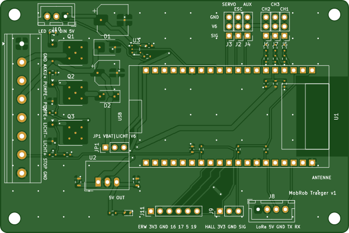
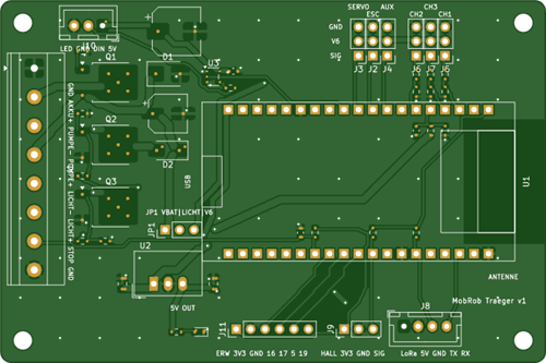
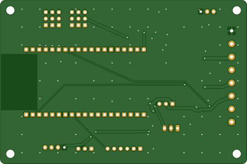
MobRob carrier board v1 - 2-layer carrier PCB for an ESP32 DevKit (38-pin) on an outdoor robot.
Hobby project, 5 pcs, standard FR-4.
PCB
- Size 96 x 64 mm, 4 corners R 2 mm, 4 mounting holes 3.2 mm (non-plated, NPTH in the drill file).
- 2 layers, FR-4 TG150, 1.6 mm, 1 oz copper, HASL lead-free (ENIG is fine too).
- Solder mask both sides (green), silkscreen top only (white), bottom silkscreen file is empty.
- Min. track 0.3 mm, min. spacing 0.2 mm, smallest hole 0.4 mm (vias 0.8/0.4 mm), vias tented.
- Gerber RS-274X (KiCad 10, Protel extensions), Excellon drill in mm, decimal, PTH + NPTH in one file.
Outline: traegerplatine-Edge_Cuts.gm1. README.txt in the ZIP repeats these specs.
- No impedance control, no castellations, no V-cut, single pieces.
Assembly (if ordered)
- Top side only, 46 placements: 32 SMD parts (0603/0805 passives, SMD electrolytics, SMA/SMB diodes,
3x TO-252, 1x SOT-23-5) plus THT connectors, a SIP-3 DC/DC module and two 1x19 female headers.
- BOM: pcbway_bom.xlsx (manufacturer part numbers). Equivalent substitutes with the same value,
package and voltage rating are acceptable - please list them for approval.
- Centroid file: pcbway_cpl.csv, mm, same origin as the Gerbers (top-left corner, Y negative downward).
- Polarity: D1, D2, D3 cathode (pin 1) and C1, C4 plus as marked on the silkscreen and in
bestueckung_oben.pdf. Q1-Q3 (TO-252): tab toward board center, leads toward the terminal block.
U3 (SOT-23-5) pin 1 marked on silkscreen.
- U1 is the ESP32 DevKit itself: do NOT populate a module, only solder the two 1x19 female headers
(2.54 mm pitch, rows 25.4 mm apart) listed in the BOM.
- JP1 is a 1x3 pin header; please include one loose 2.54 mm jumper.
- Lead-free assembly, no conformal coating, no functional test needed.
MobRobESP32
Project images are for reference only. Actual production is based on the manufacturing files on the project page.
Please review the designer's notes (e.g., PCB thickness) and select the appropriate options.
PCBWay is not responsible
for issues caused by unsuitable parameter selections.
For more important ordering information, please refer to
Read More


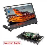
Raspberry Pi 5 7 Inch Touch Screen IPS 1024x600 HD LCD HDMI-compatible Display for RPI 4B 3B+ OPI 5 AIDA64 PC Secondary Screen(Without Speaker)
BUY NOW

- Comments(0)
- Likes(0)
 More by Engineer
-
Émetteur Récepteur Optique Expérimental (communication UART ATtiny + fibre optique)
210 0 1 -
SmallOLED - Live PC Stats, Animated Clocks & Audio Visualizer
1097 0 3 -
"Talking Multimeter": Arduino-Based Speech Add-on for Multimeters with SCPI Protocol
633 0 1 -
Programmable Mist Maker - XIAO / QT PY Extension
3100 2 3 -
RadioHAT - Raspberry Pi radio development platform
2645 0 4 -
-