




|
KiCad 8.0KiCad
|
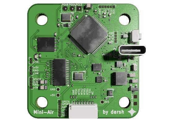
Mini-Air FPV Flight Controller
MINI-AIR FC
A 41 x 42 mm Betaflight flight controller designed from scratch — F405, ICM-42688-P gyro, analog OSD, blackbox flash, and a full 2S power tree on a board the size of a postage stamp.
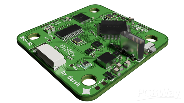
Mini-Air FC is the custom flight controller for a 2-inch FPV drone I designed and built from nothing.
I'm a 17-year-old high school student in Ontario, Canada. I've been writing software since I was 11 and building hardware for about a year, all of it through Hack Club, the largest engineering nonprofit for teenagers in the world. A flight controller is the hardest thing I've attempted: it's mixed-signal and has to satisfy a real third-party firmware specification.
PROJECT DESCRIPTION
Mini-Air is a complete DIY FPV drone: frame, motors, ESC, camera, VTX, GPS, ELRS receiver, and the flight controller at the centre of it is entirely my own design. It runs stock Betaflight. Every subsystem that a commercial FC has, this board has: gyro, on-board OSD video overlay, blackbox logging flash, battery and current telemetry, USB configuration, and a full switching power tree off a raw 2S LiPo.
The design brief was speed over range: 2S, 1103 7000 KV motors, 2-inch props, and an all-analog video chain, because analog is lower latency than digital and 480p with an OSD overlay is the look I wanted. Everything except the flight controller is off-the-shelf and modular. The flight controller is the part I wanted to actually understand.
MCU | STM32F405RGT6 — Cortex-M4F, 168 MHz, LQFP-64
Board | 41.0 x 42.0 mm, 2-layer, 1.6 mm, 3.9 g
Components | 101 placed parts: 86 SMD, all on the top side, one stencil and one reflow pass
Power | 2S LiPo (6.0 - 8.4 V) direct, plus USB-C for bench work
Mounting | 30.5 x 30.5 mm M4 pattern, oversized holes for silicone soft-mount inserts
Routing | 110 nets, 100 % routed, 0 DRC violations, 0 unconnected items
Licence | CERN-OHL-W v2, open source hardware OSHWA-certified CA000079, https://github.com/darshg321/Mini-Air
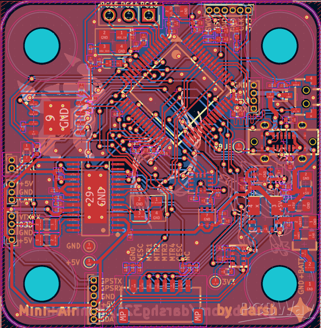
SYSTEM ARCHITECTURE
Power Tree:
The board takes an unregulated 2S pack straight onto solder pads and does everything itself:
A P-channel MOSFET (AO3401A) sits in the positive line as a reverse-polarity block with roughly 40 mV of drop: plugging the pack in backwards costs nothing instead of destroying the board. From there a TI TPSM84209 power module: a 2.5 A, 750 kHz synchronous buck with the inductor integrated, generates the 5 V rail that feeds the video transmitter, camera, GPS, receiver and OSD chip.
Two separate LP5912 LDOs then generate 3.3 V. That is deliberate, and it is the single most important power decision on the board: Betaflight's manufacturer guidelines require a dedicated regulator for the ICM-42688-P gyro, with a noise target under 50 µV peak-to-peak. So U3 runs the MCU, flash, and LEDs, and U8 runs nothing but the gyro. A noisy 3.3 V rail is a noisy gyro, and a noisy gyro is a drone that shakes itself apart.
USB VBUS reaches the 5 V rail through a Schottky diode for bench configuration with no battery connected, and four test points let every rail be probed independently with a multimeter.
Motion Sensing:
A TDK ICM-42688-P six-axis IMU on its own SPI bus, its own regulator, and its own interrupt line, mounted at the centre of the board.
A BMP280 barometer footprint sits alongside it on I2C, sharing the bus with the compass on the GPS module at the address Betaflight expects. Battery voltage is divided 100 k / 10 k: the exact ratio Betaflight's guidelines name as recommended, and current sense comes back from the ESC on a second ADC channel, both with 100 nF bypass caps on the ADC pins as the guidelines require.
Analog OSD - Video Overlay Generated On-Board:
An AT7456E on-screen-display controller sits in series with the video path: the analog camera comes in on one connector, the chip overlays battery voltage, current, timers, artificial horizon and GPS data, and the composite signal leaves through a 75 Ω back-terminated output to the video transmitter. That's a 27 MHz crystal, three open-drain sync lines pulled up, separate bypassing on all three supply domains, and AC coupling on both ends of the chain: precision analog video design, done in discrete parts, so the pilot sees flight data burned into the picture in their goggles.
The 3.3 V MCU talks to a 5 V video chip directly, which is safe here because the AT7456E specifies absolute TTL thresholds (2.0 V / 0.8 V) rather than supply-relative ones, and the return path lands on 5 V-tolerant STM32 pins. That kind of detail is exactly what I wanted to learn by building this.
Three Independent SPI Buses:
Betaflight's guidelines state plainly that it does not support sharing devices on an SPI bus. So the board gives each device its own:
- SPI1 - ICM-42688-P gyro
- SPI2 - W25Q128 128 Mbit blackbox flash (16 MB, double Betaflight's 8 MB minimum)
- SPI3 - AT7456E OSD
Nothing shares, nothing arbitrates, nothing gets corrupted by a badly timed chip select. On a 41 x 42 mm 2-layer board, giving up three sets of pins to avoid one class of bug is a real trade that I made on purpose.
Motor Outputs:
All four motor outputs sit on PC6-PC9: one GPIO port, and a set of pins that maps onto two different 4-channel timers. Betaflight requires M1-M4 on a single port for bitbang DShot to work at all, and the timer overlap means the target has a fallback if one timer is claimed elsewhere. The 8-pin ESC harness connector carries the four motor signals plus battery voltage sense and current sense back from a 4-in-1 ESC running Bluejay.
Connectivity:
| J1 | Battery solder pads, raw 2S in
| J2 | 4-in-1 ESC harness: M1-M4, V_ESC, C_ESC
| J3 | SWD debug: SWDIO, SWCLK, SWO, NRST, 3V3, GND
| J4 | Spare GPIO (PC13/14/15)
| J5 | GPS + compass: USART1 and I2C on one plug
| J7 | ELRS receiver, CRSF over UART5
| J8 | Camera: video in, 5 V, GND
| J9 | Camera OSD joystick control
| J11 | Video transmitter: video out, 5 V, and IRC Tramp control
Plus USB-C: full-speed USB device with the correct 5.1 kΩ CC pull-downs, giving DFU firmware flashing and Betaflight Configurator over a single cable, with SWD kept as the guaranteed fallback path.
Designed for Betaflight Specification:
This is the part I'm proudest of. Betaflight publishes manufacturer design guideline: the rules commercial flight controller vendors are meant to build to. I reviewed this board line by line against them:
| Gyro must be SPI, never I2C | SPI1, dedicated bus
| ICM-42688-P strongly recommended | ICM-42688-P
| Dedicated LDO required for the gyro | LP5912, gyro only
| M1-M4 on a single GPIO port | PC6-PC9, all GPIOC
| VBAT divider 100 k / 10 k | Exact match
| Blackbox flash 8 MB minimum | 16 MB
| No SPI bus sharing | Three separate buses
| QMC5883L compass preferred | QMC5883 on the GPS module
| 100 nF on every ADC input | Present on both
| 30.5 x 30.5 M4 holes, soft-mounted | Exact match
| SWD test points beneficial | Full 6-pin debug header
Where the board doesn't meet a guideline, I know exactly where and why, and it's written down: a 41 x 42 mm 2-layer board built by one student has to make compromises, and documenting them honestly is part of the engineering.
PCB DESIGN
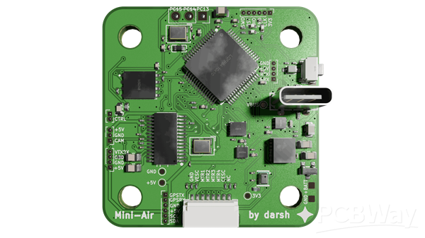
| Layers | 2, 1.6 mm
| Board size | 41.0 x 42.0 mm
| Nets | 110, 100 % routed
| Tracks | 990 segments, 1400 mm total copper
| Min track width | 0.15 mm
| Vias | 165 at 0.6 / 0.3 mm
| Assembly | Single-sided, 86 SMD parts, one stencil, one reflow
| Fine pitch | 0.5 mm LQFP-64, LGA-14, WSON, QFN
Fitting a switching regulator, two LDOs, a 168 MHz MCU, an analog video chain, three SPI buses, USB, and nine connectors into 1722 mm² on two layers was the hardest layout problem I've worked on. Crystal load caps sit 1.5-1.8 mm from their pins, the MCU's VCAP capacitors within 1.7 mm, and every VDD pin has its own bypass within 1.6 mm.
The FPV Drone:
| Frame | AlfaRC APEX 2 V4, 95 mm wheelbase, 2-inch props
| Motors | 4x HappyModel EX1103S, 7000 KV
| ESC | HAKRC 15 A 4-in-1, Bluejay firmware
| Video | Caddx Ant Lite analog camera, 5.8 GHz 400 mW VTX
| Control | ExpressLRS 2.4 GHz
| Nav | M10 GNSS with compass
| Battery | 2S 450 mAh 75C
| All-up | 88 g
Why This Matters:
I'm a high school student building this on personal time and a student budget. The fabrication and assembly cost is the thing standing between a design that exists in KiCad and a drone that flies, and unlike a dev board, a flight controller either works in the air or it doesn't, so it has to be built properly the first time.
Sponsoring this board would let me finish it at the quality the design deserves and then show other teenagers the whole thing: the schematic, the review, the mistakes, the quote correspondence, and a drone in the air at the end of it. Mini-Air will be documented with a public repo under an open hardware licence (verified on OSHWA https://certification.oshwa.org/ca000079.html), a build writeup with PCBWay credited, posts in the Hack Club Slack where over 100,000 teenagers building hardware will see it, and a place in the printed materials at FraserHacks in Spring 2027.
Thank you for considering Mini-Air FC for sponsorship.
Mini-Air FPV Flight Controller
Project images are for reference only. Actual production is based on the manufacturing files on the project page.
Please review the designer's notes (e.g., PCB thickness) and select the appropriate options.
PCBWay is not responsible
for issues caused by unsuitable parameter selections.
For more important ordering information, please refer to
Read More









Raspberry Pi 5 7 Inch Touch Screen IPS 1024x600 HD LCD HDMI-compatible Display for RPI 4B 3B+ OPI 5 AIDA64 PC Secondary Screen(Without Speaker)
BUY NOW


- Comments(0)
- Likes(1)
More by Darsh Gupta
-
SmallOLED - Live PC Stats, Animated Clocks & Audio Visualizer
621 0 3 -
"Talking Multimeter": Arduino-Based Speech Add-on for Multimeters with SCPI Protocol
352 0 1 -
Programmable Mist Maker - XIAO / QT PY Extension
2793 2 3 -
RadioHAT - Raspberry Pi radio development platform
2395 0 4 -
-
-
-
ARPS-2 – Arduino-Compatible Robot Project Shield for Arduino UNO
4489 0 6


















