


Logic gate learning kit
The Project
In this project you will learn how to build your own logic gate learning kit and learn all about the different logic gates.
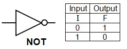
NOT
A NOT gate is used to invert a signal. Below is a truth table and drawing of the logic gate.
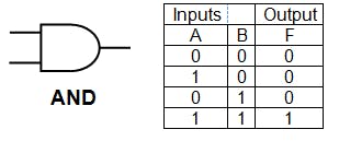
AND
An AND gate is used to take 2 or more signals and only turn on the output when all the inputs are on. Below is a truth table and drawing of the logic gate.
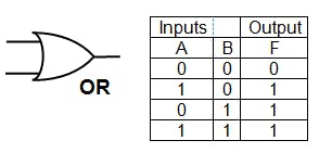
OR
An OR gate is used to take 2 or more signals and only turn on the output when all 1 or all of the inputs are on. Below is a truth table and drawing of the logic gate.
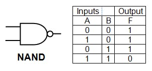
NAND
An NAND gate is used to take 2 or more signals and only turn on the output when all the inputs are off. Below is a truth table and drawing of the logic gate.
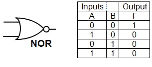
NOR
An NOR gate is used to take 2 or more signals and only turn on the output when all of the inputs are off. Below is a truth table and drawing of the logic gate.
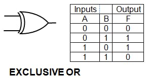
XOR
An XOR gate is used to take 2 or more signals and only turn on the output when 1 of the inputs are on only. Below is a truth table and drawing of the logic gate.
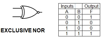
XNOR
An XNOR gate is used to take 2 or more signals and only turn on the output when all none are off only. Below is a truth table and drawing of the logic gate.
Learning kit
This learning kit will allow the user to learn how logic gates work hands on so great for beginners. The kit has all the logic gates on and allows the user to experiments with the different logic gates. Figure 1 is the schematic for the kit. (sorry the schematic is badly done)
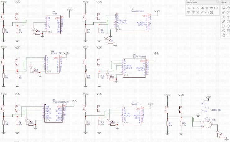
Figure 1 - Schematic
Figure 2 is a picture of the PCB that can be manufactured.
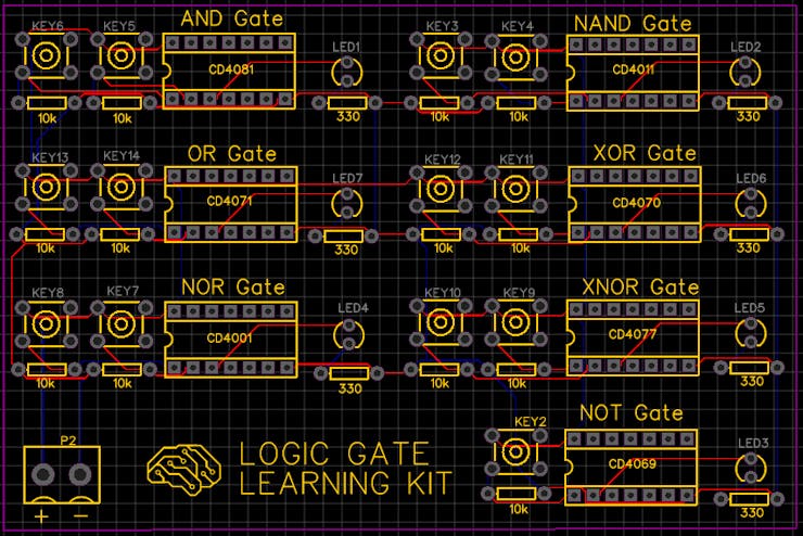
Figure 2 - PCB
Website
Check out more of my other projects on my website.
Logic gate learning kit
Project images are for reference only. Actual production is based on the manufacturing files on the project page.
Please review the designer's notes (e.g., PCB thickness) and select the appropriate options.
PCBWay is not responsible
for issues caused by unsuitable parameter selections.
For more important ordering information, please refer to
Read More


Raspberry Pi 5 7 Inch Touch Screen IPS 1024x600 HD LCD HDMI-compatible Display for RPI 4B 3B+ OPI 5 AIDA64 PC Secondary Screen(Without Speaker)
BUY NOW


- Comments(5)
- Likes(9)
- 16 USER VOTES
- YOUR VOTE 0.00 0.00

-
6design
-
8usability
-
8creativity
-
9content

-
6design
-
8usability
-
6creativity
-
7content

-
6design
-
5usability
-
4creativity
-
6content

-
8design
-
9usability
-
8creativity
-
9content

-
7design
-
8usability
-
8creativity
-
8content

-
8design
-
7usability
-
7creativity
-
2content
-
8design
-
7usability
-
7creativity
-
6content

-
5design
-
9usability
-
8creativity
-
10content

-
7design
-
7usability
-
7creativity
-
7content

-
8design
-
9usability
-
8creativity
-
7content

-
7design
-
8usability
-
6creativity
-
9content

-
7design
-
7usability
-
6creativity
-
9content
-
6design
-
4usability
-
2creativity
-
3content
-
4design
-
4usability
-
2creativity
-
5content
-
2design
-
4usability
-
1creativity
-
1content
-
10design
-
10usability
-
10creativity
-
10content
More by . .
-
 Logic gate learning kit
The ProjectIn this project you will learn how to build your own logic gate learning kit and learn al...
Logic gate learning kit
The ProjectIn this project you will learn how to build your own logic gate learning kit and learn al...
-
 Battery Level Indicator/Alarm
In this project learn how to make an LED battery level indicator using an LM3914 and some LEDs. The ...
Battery Level Indicator/Alarm
In this project learn how to make an LED battery level indicator using an LM3914 and some LEDs. The ...
-
 DIY Power Bank
In this project I will show you how to build a simple DIY battery bank that can charge USB devices.T...
DIY Power Bank
In this project I will show you how to build a simple DIY battery bank that can charge USB devices.T...
-
 ohmega bauble
bauble with LEDs that can be programed to display different patterns
ohmega bauble
bauble with LEDs that can be programed to display different patterns
-
 100 QFP to DIP
 100 adapter
100 QFP to DIP
100 QFP to DIP 100 adapter
-
Programmable Mist Maker - XIAO / QT PY Extension
1067 2 1 -
RadioHAT - Raspberry Pi radio development platform
883 0 2 -
-
-
-
-
ARPS-2 – Arduino-Compatible Robot Project Shield for Arduino UNO
3332 0 6 -
A Compact Charging Breakout Board For Waveshare ESP32-C3
3941 3 8 -
AI-driven LoRa & LLM-enabled Kiosk & Food Delivery System
4327 2 2


