
|
KiCADKicad
|
|

|
Visual Studio Code |
|
|
Raspberry Pi Pico SDKRaspberry Pi Foundation
|
|
|
|
ESP-IDF |
ILDAWaveX16 V2
Introduction
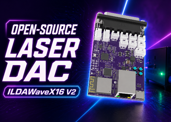
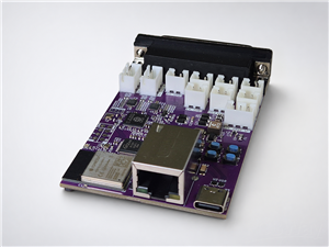
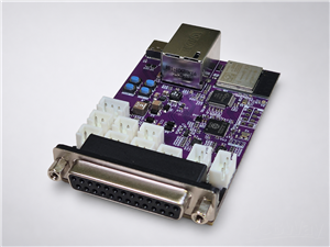
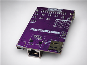
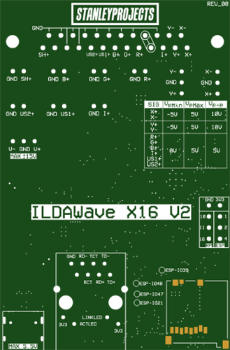
ILDAWaveX16 V2 is an open-source, high-resolution laser DAC for laser enthusiasts. Built around a dual-processor ESP32-S3 + RP2354 architecture, it combines standard ILDA DB25 output, direct pin headers for easy integration, SD-card playback, Ethernet/Wi-Fi/USB connectivity, and support for a wide range of real-time streaming protocols.
It is a universal laser DAC platform: an all-in-one, flexible, and hackable laser control board. It is open, modifiable, and easy to build on, without locking users into proprietary protocols, closed tools, or fixed workflows. Whether you want to integrate it inside a projector, experiment with new protocols, or learn how laser control works, ILDAWaveX16 V2 is made to be explored, modified, and extended.
Full documentation is available at
Hardware
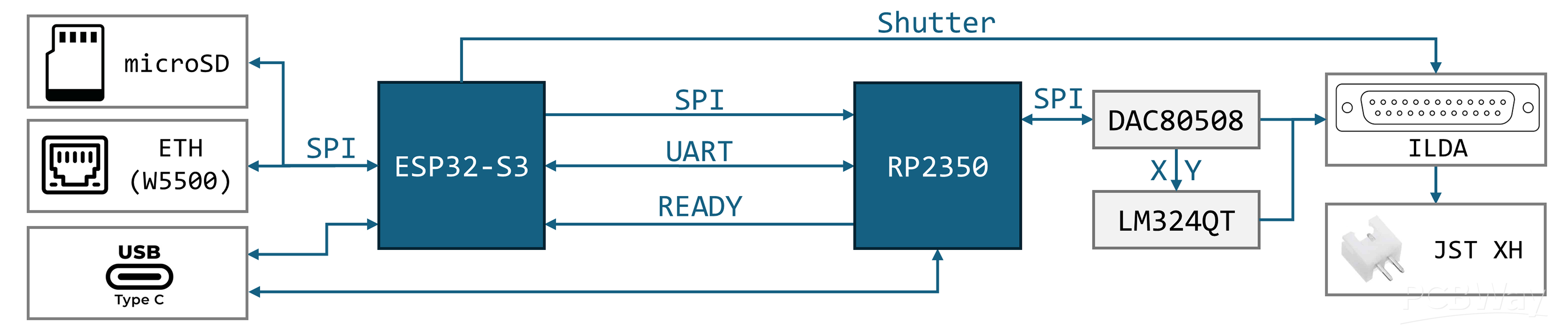
ILDAWaveX16 V2 uses two dual-core processors. The ESP32-S3 handles the user-facing side of the board, including the web UI, Wi-Fi, Ethernet, SD-card playback, protocol handling, and configuration. The RP2354A is dedicated to deterministic real-time sample output, keeping DAC timing stable while the ESP32-S3 handles communication and control.
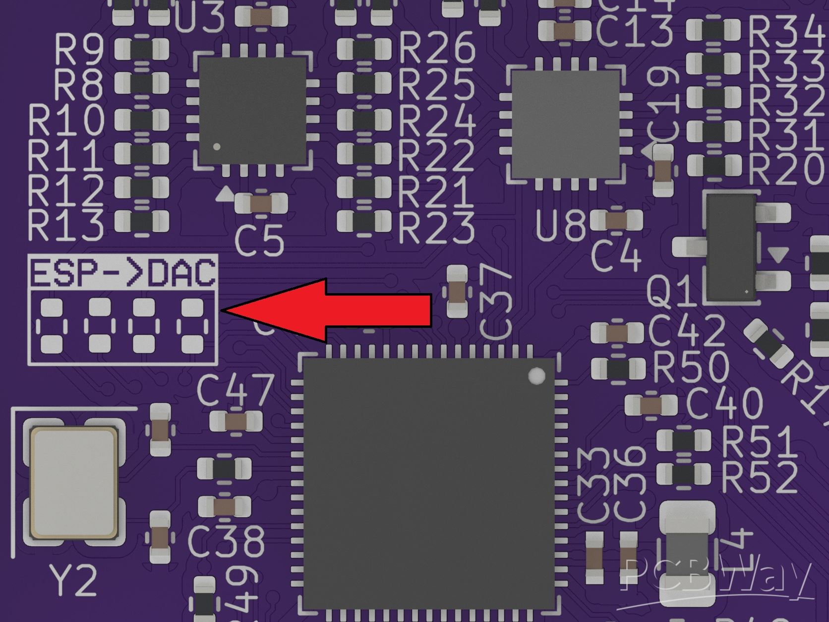
If a single-processor setup is ever needed, bridge the four individual solder jumpers labeled ESP->DAC vertically, and flash the RP2354 with firmware that leaves all GPIOs in a high-impedance state.
Both processors can be accessed through the same USB-C connector. The board routes the USB lines depending on the cable orientation, allowing either the ESP32-S3 or the RP2354A to be programmed or debugged without adding a second USB port. This keeps the board compact while still making both processors accessible during development.
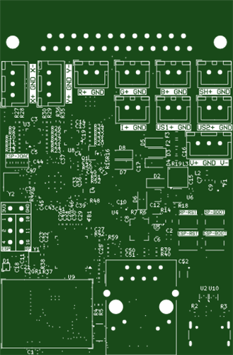
The ESP32-S3 provides built-in Wi-Fi, while a W5500 Ethernet controller adds wired networking for lower-latency streaming. The board also includes a microSD card slot, ESD protection, a status LED, user buttons, exposed GPIOs, and connector options for ILDA DB25 output and JST XH for direct connections to galvo/laser driver kits.
Power can be supplied from 5V USB-C or from an optional external bipolar power supply up to ±15V. Protection circuitry allows both power sources to be connected at the same time, which is useful during programming and testing. The board uses a TLV61048-based supply to generate ±8V analog rails, and TPS62160/NCP167 regulators to generate the 5V and 3.3V digital rails for the ESP32-S3, RP2354A, Ethernet controller, DAC, and logic.
The analog output stage is built around a DAC80508, an 8-channel 16-bit SPI DAC. Its channels are used for X, Y, red, green, blue, intensity, and two user-defined outputs. To produce ILDA-style output levels, the X and Y channels pass through a two-stage op-amp circuit, and all analog output signals are terminated with 150Ω resistors according to the ILDA specification. The board also provides a shutter output implemented as a high-side switch, producing a 0V or 5V on/off signal.
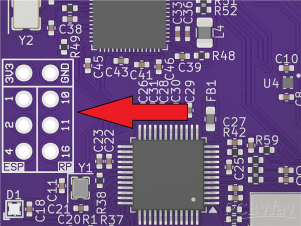
The board also exposes three GPIO pins from the ESP32-S3 and three GPIO pins from the RP2354, allowing users to add custom controls, indicators, triggers, sensors, or other project-specific extensions.
Diagram
Firmware
The ILDAWaveX16 V2 firmware is split into two projects: one for the ESP32-S3 and one for the RP2354. For firmware development, I recommend using Visual Studio Code with the ESP-IDF extension for the ESP32-S3 project, and the Raspberry Pi Pico extension for the RP2354 project.
Flashing the firmware
Both microcontrollers are connected to the same USB-C port. Depending on the cable orientation, the USB-C port connects either to the ESP32-S3 or to the RP2354. If your computer does not detect the controller you want to flash, unplug the USB-C cable, rotate it 180°, and plug it in again.
Firmware Architecture
ILDAWaveX16 V2 is a dual-MCU laser DAC system built around an ESP32-S3 control processor and an RP2354 real-time output engine. The ESP32-S3 handles networking, protocol parsing, SD-card playback, web configuration, test-pattern generation, and high-level stream management. The RP2354 is dedicated to deterministic sample output, buffering incoming laser frames and driving the physical DAC hardware with precise timing. This split architecture keeps protocol and UI workloads isolated from the real-time laser output path.
Incoming data from SD files, test patterns, USB, or network protocols is converted on the ESP32-S3 into a unified internal sample format. Each laser point is represented as an 8-channel signed 16-bit sample: X, Y, red, green, blue, intensity, us1, and us2.
The ESP32-S3 and RP2354 communicate through SPI, UART, and a READY synchronization signal. UART is used for command and control, while SPI is used for high-speed payload transfer. The ESP32-S3 sends fixed-size stream packets containing a header, sequence number, sample count, payload checksum, and a block of packed 8-channel sample data.
On the RP2354 side, a PIO-based SPI receiver captures incoming packets, DMA transfers the bytes into memory, validates the magic header, checks the sample count, verifies the checksum, and pushes valid samples into the output ring buffer. The buffer is runtime-configurable from the web interface, including buffer size, high-water threshold, and low-water threshold.
The READY GPIO acts as hardware-level flow control. The RP2354 raises READY when it can accept another SPI packet and lowers it when the output ring buffer reaches the configured high-water mark. Once the fill level falls below the low-water mark, the RP2354 raises READY again and resumes accepting packets. This hysteresis helps prevent constant start/stop oscillation during streaming.
The RP2354 drives the physical DAC over SPI. The DAC engine writes all 8 channels and then issues a synchronized update so the analog outputs change together. X/Y mirroring is also handled in the RP2354 firmware, allowing the scanner coordinate system to be flipped without modifying source content or laser show software.
The output engine includes underrun and failsafe behavior. During an active underrun, the firmware does not immediately force X/Y to zero; instead, it holds the last valid scanner position and blanks the laser channels. This avoids visible scanner jumps and unwanted artifacts during unstable input streams. If output is stopped completely, all DAC channels are driven to a hard zero state.
Protocols and Playback
SD Card Playback
The ESP32-S3 can play .ild files directly from microSD. It parses ILDA coordinate and color formats, converts indexed or true-color ILDA data into RGB/intensity output samples, and streams the converted data to the RP2354 through the same SPI payload path used by live protocols.
The current implementation loads converted frames into PSRAM-backed memory, which makes playback fast (≥100 kpps) and stable, but limits the maximum file size that can be played. A future improvement would be continuous batch reading, where only partial chunks of the ILDA file are read, converted, and streamed at a time so larger files can be played without loading the full converted output into memory.
IDN / ILDA Digital Network
The firmware includes an IDN / ILDA Digital Network implementation over UDP. It supports IDN-Hello discovery, allowing compatible software to find the device on the network. Once connected, incoming IDN real-time stream data is parsed, converted into the internal 8-channel sample format, and forwarded to the RP2354 output engine.
The current implementation is functional and useful for experimentation, compatibility testing, and further development. However, it still needs optimization to reach higher point rates reliably without dropouts. It should be treated as a working starting point for IDN support rather than a fully optimized final implementation.
Ether Dream
The firmware includes an Ether Dream compatible DAC server, allowing standard laser software to discover and stream point data to the board. It implements UDP discovery, TCP control and streaming, point-rate configuration, prepare/start/stop behavior, and Ether Dream point conversion into the internal 8-channel sample format.
Similar to IDN, this protocol path works, but still needs optimization at higher point rates. Depending on sender behavior, packet size, network path, and buffer configuration, high-rate network streaming can still run into buffer underruns, or transport bottlenecks.
USB Protocols
Both the ESP32-S3 and RP2354 have native USB, so the board can also be used for USB-based applications. As a proof of concept, a Helios DAC USB protocol was implemented, allowing the board to be recognized by compatible software, and receive point data over USB.
Due to licensing concerns, the Helios DAC USB implementation is not included in the public firmware. However, the proof of concept shows that the hardware is suitable for custom USB protocol development, including USB streaming as an alternative to network streaming.
Web Interface and REST API
The ESP32-S3 serves an embedded web dashboard for runtime control, configuration, and diagnostics. From the browser, you can start and stop output, clear the RP2354 buffer, set the sample rate, configure buffer size and watermarks, enable X/Y mirroring, start built-in test patterns, set the test color mask, play ILDA files from SD, enable or disable network protocols, configure Ethernet and Wi-Fi settings, reboot the board, and restore factory settings.
The dashboard also displays live system state, including RP2354 firmware status, buffer fill, sample rate, underruns, payload errors, dropped packets, stream counters, network state, and SD-card file listings.
Networking
The ESP32-S3 firmware supports both wired and wireless configuration paths. Ethernet is handled through the W5500 SPI Ethernet controller (10/100 Base-T/TX), while Wi-Fi can operate in AP or STA mode. The device also provides mDNS discovery and setup-friendly access point behavior for easier configuration.
Network configuration supports DHCP and static IP settings. For real-time streaming, wired Ethernet is recommended, and Wi-Fi can be disabled in settings when Ethernet is used.
ILDAWaveX16 V2
Project images are for reference only. Actual production is based on the manufacturing files on the project page.
Please review the designer's notes (e.g., PCB thickness) and select the appropriate options.
PCBWay is not responsible
for issues caused by unsuitable parameter selections.
For more important ordering information, please refer to
Read More









Raspberry Pi 5 7 Inch Touch Screen IPS 1024x600 HD LCD HDMI-compatible Display for RPI 4B 3B+ OPI 5 AIDA64 PC Secondary Screen(Without Speaker)
BUY NOW


- Comments(2)
- Likes(9)


More by StanleyProjects
-
 ILDAWaveX16 | StanleyProjects.com
ILDAWaveX16 is an open-source, high-resolution, wireless laser DAC with SD-card playback, network co...
ILDAWaveX16 | StanleyProjects.com
ILDAWaveX16 is an open-source, high-resolution, wireless laser DAC with SD-card playback, network co...
-
 ILDAWaveX16 V2
IntroductionILDAWaveX16 V2 is an open-source, high-resolution laser DAC for laser enthusiasts. Built...
ILDAWaveX16 V2
IntroductionILDAWaveX16 V2 is an open-source, high-resolution laser DAC for laser enthusiasts. Built...
-
 LaserProjector V2 | StanleyProjects.com
LaserProjector V2 is a battery-powered, ESP32-based laser XY scanner using stepper motors to deflect...
LaserProjector V2 | StanleyProjects.com
LaserProjector V2 is a battery-powered, ESP32-based laser XY scanner using stepper motors to deflect...
-
 LedBox V2 | StanleyProjects.com
IntroductionLedBox V2 is a fully contained, sound reactive, ESP32 based module for controlling 5-12V...
LedBox V2 | StanleyProjects.com
IntroductionLedBox V2 is a fully contained, sound reactive, ESP32 based module for controlling 5-12V...
-
Émetteur Récepteur Optique Expérimental (communication UART ATtiny + fibre optique)
138 0 1 -
SmallOLED - Live PC Stats, Animated Clocks & Audio Visualizer
983 0 3 -
"Talking Multimeter": Arduino-Based Speech Add-on for Multimeters with SCPI Protocol
561 0 1 -
Programmable Mist Maker - XIAO / QT PY Extension
3033 2 3 -
RadioHAT - Raspberry Pi radio development platform
2582 0 4 -
-
-