


|
|
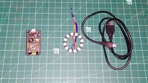
ESP8266EXESPRESSIF(乐鑫)
|
x 1 | |

|
RGB LED Ring |
x 1 | |
|
422001 BK005Alpha Wire
|
x 1 |

|
arduino IDEArduino
|
ESP 8266 Nodemcu Ws 2812 Neopixel Based LED MOOD Lamp Controlled by Local Web Server
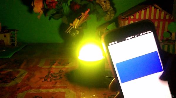
The most popular decorative item used during Festivals like Eid, Christmas & Diwali are LEDs. The LED light during the night makes everything looks beautiful. But most of the LED available only produce a single colour. So to create a multicolour beautiful light pattern we can use RGB LED. But here we will create such pattern ourselves using multiple colours LED.
We will use WS2812B Neopixel RGB LED and interface it with NodeMCU ESP8266 Board. With the help of wifi network, we will control RGB LED Strip wirelessly from anywhere. We will download the Blynk Android app from play store and configure it for controlling LED Pattern, colour & brightness. We will learn about the working principle of WS2812B RGB LED.

Setting up the Blynk Android App
Blynk is an application that runs over Android and IOS devices to control any IoT based application using Smartphones. It allows you to create your Graphical user interface for IoT application. Here we will set up the Blynk application to control NeoPixel LED over Wi-Fi using NodeMCU ESP8266.

So download and install the Blynk Application from Google Play store. IOS users can download from the App Store. Once the installation is completed, open the app & sign-up using your Email id and Password.

Now click on “New Project”. In the pop up set the parameters like Project name, Board and connection type as shown in the photo above. For this NeoPixel ESP8266 project select the device as NodeMCU and connection type as Wi-Fi. Then click on Create.
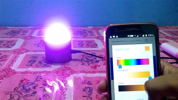
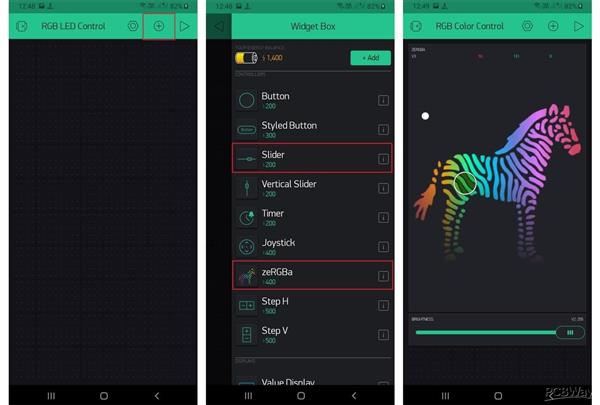
Now click on the “+” sign to add the widgets. We need an RGB Color Picker which is listed as “zeRGBa” and a slider to control the brightness of the LED strip.
After dragging the widgets, set their parameters as shown in image above. Click on ZeRGBa set the Output option to “Merge” and set the pin to “V3”. Similarly, in Slider settings, set the output pin to “V2.”
After the successful creation of the Project, go back to setting and click on Send Email. You will get an Authenticate ID on registered mail. Save the Authenticate ID for future reference.
Source Code/Program
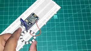
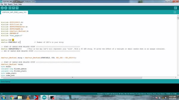
Once the hardware setup is done, now we need to upload the code to the NodeMCU ESP8266-12E Board. But before that you need to install 2 libraries.
1. FastLED.h Library: Download
2. BlynkSimpleEsp8266.h Library: Download
Also before uploading the code make sure to make the following changes in the code. Change the Authenticate ID, WiFi SSID & Password.
#define BLYNK_PRINT Serial
#include <BlynkSimpleEsp8266.h>
#define FASTLED_ESP8266_RAW_PIN_ORDER
#include "FastLED.h"
#define NUM_LEDS1 60
#define LED_TYPE WS2812
#define COLOR_ORDER GRB
CRGB leds1[NUM_LEDS1];
char auth[] = "8aZvLCBN36c90JivMOW2btEkBNjQvGOS";
char ssid[] = "Fimo";
char pass[] = "Fimo@!23";
#define PIN1 D1
int data=255;
int r,g,b;
void setup()
{
Serial.begin(9600);
Blynk.begin(auth, ssid, pass);
FastLED.addLeds<LED_TYPE, PIN1, COLOR_ORDER>(leds1, NUM_LEDS1).setCorrection( TypicalLEDStrip );
}
BLYNK_WRITE(V3)
{
r = param[0].asInt();
g = param[1].asInt();
b = param[2].asInt();
static1(r, g, b,data);
}
void loop()
{
Blynk.run();
}
BLYNK_WRITE(V2)
{
data = param.asInt();
static1(r, g, b,data);
}
void static1(int r, int g, int b,int brightness)
{
FastLED.setBrightness(brightness);
for (int i = 0; i < NUM_LEDS1; i++ )
{
leds1[i] = CRGB(r, g, b);
}
FastLED.show();
}
Make sure you also install the neopixel library for Arduino if you haven't already. Get it using the library manager
In the Arduino Go to Sketch --> Include Library --> Manage Libraries (it's at the top of the list)
Type "neopixel" in the search box
select the Adafruit neopixel library and install
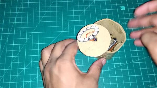
Now get your sketch ready. You can use the generic StrandTest sketch in the examples menu under the Adafruit NeoPixel folder. Set the number of pixels you're using and set the data pin - I'm using pin 14.
[NOTE: DON'T USE PIN 16 FOR NEOPIXELS].
Put the board in bootloader mode.
If you're using the Huzzah breakout, this means holding down the GPIO0 button, pressing and releasing the resent button, then releasing the GIO0 button.
If you're using a bare ESP8266 instead, then temporarily connect GPIO0 to ground, toggle power to the reset pin,then disconnect GPIO0 from ground.
If you've done one of the above correctly, the on-board LED should be dimly on.
Now upload the sketch using the Arduino IDE. This will take a while and you will probably see the on-board LED flicker during transfer.
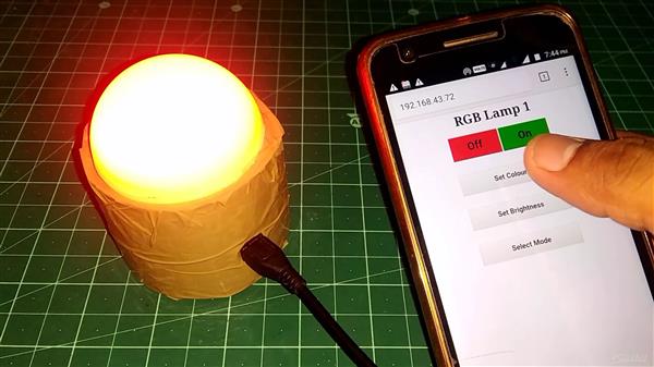
Now that you've uploaded the sketch, let's see if it works. Flip the switch on your battery and you should see your neopixels light up.
Congratulations, you're halfway to making the next big IoT device! Have fun making things light up from afar with your ESP8266.

ESP 8266 Nodemcu Ws 2812 Neopixel Based LED MOOD Lamp Controlled by Local Web Server


Raspberry Pi 5 7 Inch Touch Screen IPS 1024x600 HD LCD HDMI-compatible Display for RPI 4B 3B+ OPI 5 AIDA64 PC Secondary Screen(Without Speaker)
BUY NOW


- Comments(0)
- Likes(0)
More by electronicguru0007
-
 How to make an alarm clock with pic microcontroller
he five push buttons will act as an input for setting the alarm for the required time. So one end of...
How to make an alarm clock with pic microcontroller
he five push buttons will act as an input for setting the alarm for the required time. So one end of...
-
 How to make RMS to DC Converter using IC AD736
A True-RMS or TRMS is a type of converter which converts RMS value to equivalent DC value. Here in t...
How to make RMS to DC Converter using IC AD736
A True-RMS or TRMS is a type of converter which converts RMS value to equivalent DC value. Here in t...
-
 STM32 SPI Communcation and Data Sent
SPI in STM32F103C8Comparing SPI bus in Arduino & STM32F103C8 Blue Pill board, STM32 has 2 SPI bu...
STM32 SPI Communcation and Data Sent
SPI in STM32F103C8Comparing SPI bus in Arduino & STM32F103C8 Blue Pill board, STM32 has 2 SPI bu...
-
 How to Communicate Arduinos via RS-485
What project will you develop?The project consists of 3 Arduino's. We have an Arduino UNO, a Nano, a...
How to Communicate Arduinos via RS-485
What project will you develop?The project consists of 3 Arduino's. We have an Arduino UNO, a Nano, a...
-
 PIC16F877A Temperature and Humidity Measurement Board
Temperature and Humidity measurement is often useful in many applications like Home Automation, Envi...
PIC16F877A Temperature and Humidity Measurement Board
Temperature and Humidity measurement is often useful in many applications like Home Automation, Envi...
-
 Diy Buck Converter
n the field of DC-DC Converters, A single-ended primary-inductor converter or SEPIC converter is a t...
Diy Buck Converter
n the field of DC-DC Converters, A single-ended primary-inductor converter or SEPIC converter is a t...
-
 Iot AC Current Measuring System
Smart power monitoring is getting increasingly popular to improve energy efficiency in medium/small ...
Iot AC Current Measuring System
Smart power monitoring is getting increasingly popular to improve energy efficiency in medium/small ...
-
 ESP32 Weather Station
In this project, we will learn how to create a weather station, which will display reading from a BM...
ESP32 Weather Station
In this project, we will learn how to create a weather station, which will display reading from a BM...
-
 NRF Data Transfer Via 2 Boards
There are various wireless communication technologies used in building IoT applications and RF (Radi...
NRF Data Transfer Via 2 Boards
There are various wireless communication technologies used in building IoT applications and RF (Radi...
-
 Iot patient monitoring system
When we are talking about major vital signs of a human body, there are four major parameters that we...
Iot patient monitoring system
When we are talking about major vital signs of a human body, there are four major parameters that we...
-
 Setting up zigbee communication with nodemcu and arduino
Zigbee is a popular wireless communication protocol used to transfer a small amount of data with ver...
Setting up zigbee communication with nodemcu and arduino
Zigbee is a popular wireless communication protocol used to transfer a small amount of data with ver...
-
 Ac Dimmer Remote PCB
The brightness can be controlled using the IR remote of TV, DVD, etc. Dimming Control system using M...
Ac Dimmer Remote PCB
The brightness can be controlled using the IR remote of TV, DVD, etc. Dimming Control system using M...
-
 Esp32 Home Automation
There are relay modules whose electromagnet can be powered by 5V and with 3.3V. Both can be used wit...
Esp32 Home Automation
There are relay modules whose electromagnet can be powered by 5V and with 3.3V. Both can be used wit...
-
 Lora Communication With Network
This was a very simple project and can come in handy for various applications. But what it can't do ...
Lora Communication With Network
This was a very simple project and can come in handy for various applications. But what it can't do ...
-
 GPS Module Based Tracking Device Pcb
ESP32 GPS vehicle tracker using NEO 6M GPS module and Arduino IDE. With the help of this GPS tracker...
GPS Module Based Tracking Device Pcb
ESP32 GPS vehicle tracker using NEO 6M GPS module and Arduino IDE. With the help of this GPS tracker...
-
 Traffic Management for Emergency Vehicles using AT89S52 Microcontroller
These days’ traffic congestion is the biggest problem of densely populated cities. The project focus...
Traffic Management for Emergency Vehicles using AT89S52 Microcontroller
These days’ traffic congestion is the biggest problem of densely populated cities. The project focus...
-
 Diy Multimeter Pcb
This is a project based on Arduino board which can measureresistance, diode, continuity[H1] , voltag...
Diy Multimeter Pcb
This is a project based on Arduino board which can measureresistance, diode, continuity[H1] , voltag...
-
 Live Instagram Followers Pcb
ESP8266 is capable of functioning reliably in industrial environments, with an operating temperature...
Live Instagram Followers Pcb
ESP8266 is capable of functioning reliably in industrial environments, with an operating temperature...
-
-
ARPS-2 – Arduino-Compatible Robot Project Shield for Arduino UNO
1278 0 4 -
A Compact Charging Breakout Board For Waveshare ESP32-C3
1795 3 7 -
AI-driven LoRa & LLM-enabled Kiosk & Food Delivery System
1780 2 0 -
-
-
-
ESP32-C3 BLE Keyboard - Battery Powered with USB-C Charging
1961 0 1 -


