
|
Altium DesignerAltium Designer
|
ESP32 6-Channel 24V Smart PWM Fan Controller (WLAN/Bluetooth Ready)
Detailed Project Description
ESP32 6-Channel 24V Smart PWM Fan Controller
This project is a custom six-channel controller for 24 V four-wire PWM fans, built around an ESP32-WROOM-32E.
The goal was to create a single board that could do more than simply generate PWM signals. I wanted the controller to know whether each fan is actually running, adapt itself to the characteristics of different fans, automatically regulate cooling based on temperature, and remain configurable without needing a separate PC application.
The result combines six independent PWM fan channels, tachometer feedback, environmental sensing, automatic fan control, an optional OLED display, Wi-Fi configuration, OTA firmware updates and built-in hardware diagnostics on one PCB.
Six Independent Fan Channels
The board supports up to six standard four-wire PWM fans.
Each fan connection provides:
- 24 V power
- Ground
- PWM speed control
- Tachometer / RPM feedback
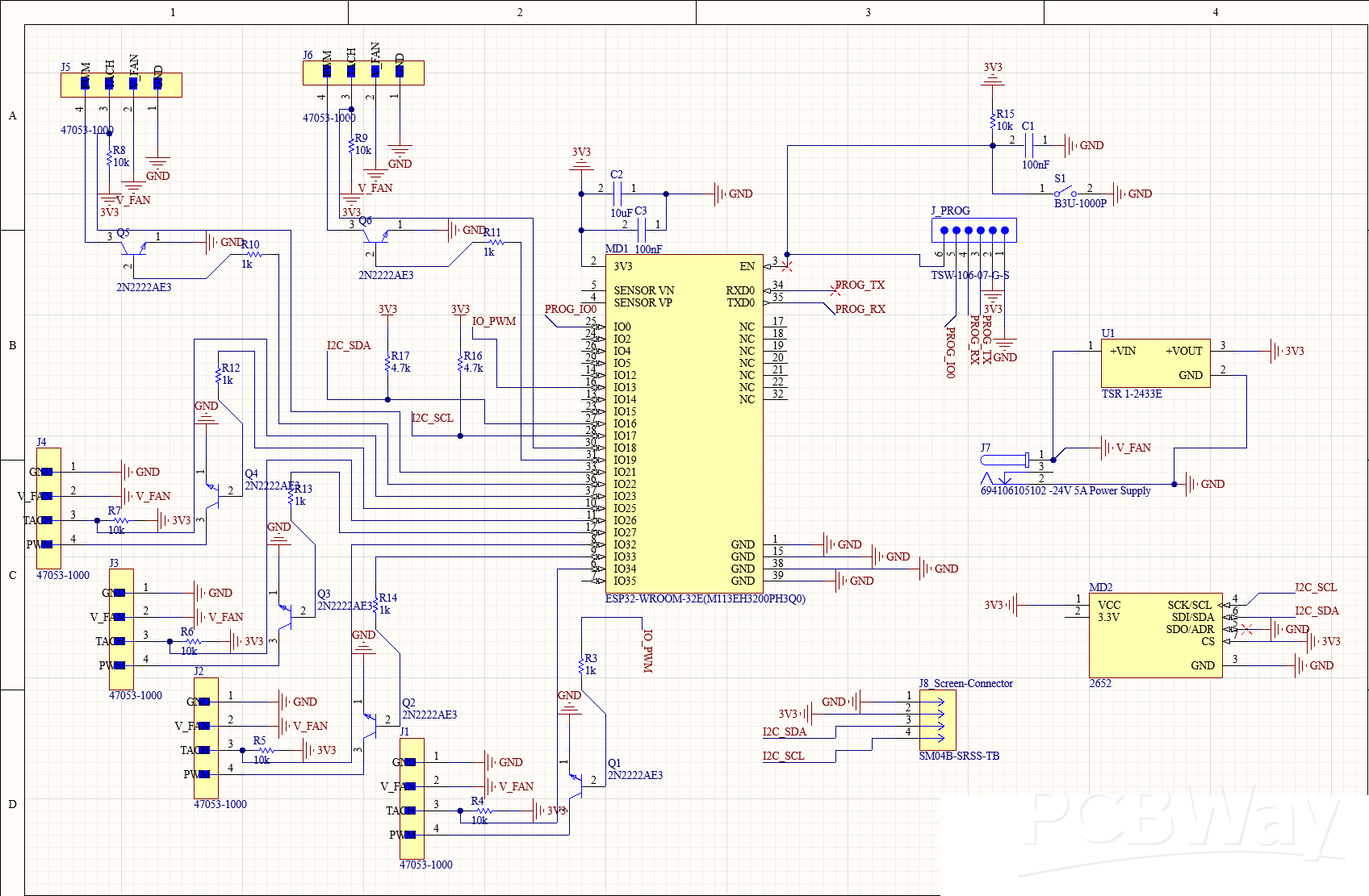
The ESP32 generates a 25 kHz PWM control signal for each fan. The PWM lines use individual 2N2222 transistor stages to provide the open-collector style interface expected by four-wire PWM fans. Every fan also has an independent tachometer input, allowing the ESP32 to measure its actual RPM. This feedback is important because the controller does not simply assume that sending a PWM value means the fan is operating at the expected speed.
Adaptive Per-Fan Calibration
One of the main features of the firmware is automatic fan calibration.
Different fans behave very differently at low PWM levels. One fan might continue running reliably at 20%, while another may stop completely below 35%. Because of this, using the raw PWM duty cycle as the user-facing speed setting is not particularly useful. During calibration, the controller first runs a fan at full speed to determine its maximum RPM. It then progressively reduces the PWM level while monitoring the tachometer signal. This allows the firmware to determine the minimum stable operating point of each individual fan as well as whether the fan supports a complete stop at 0%. The calibration data is stored in the ESP32's non-volatile memory.
After calibration, the user can simply select a fan level between 0 and 100%. The firmware maps this requested level onto the actual usable PWM range of that particular fan. This makes it possible to use different fan models while still getting predictable control behaviour.
RPM Monitoring and Fan Startup
Tachometer feedback is also used during normal operation.
When a stopped fan needs to start, the controller initially drives it at full power to ensure reliable startup. Once RPM feedback confirms that the fan is rotating, the PWM output is reduced to the requested operating level.
This avoids situations where a fan is commanded to run at a low speed but does not have enough starting torque to begin rotating.
The firmware continuously calculates and monitors the RPM of all connected fans and can detect missing tachometer feedback or abnormal fan behaviour.
Automatic Temperature Control
The board includes a BME280 environmental sensor for measuring:
- Temperature
- Relative humidity
- Atmospheric pressure
In automatic mode, the six fans are controlled according to a configurable temperature curve.
The user can define a lower and upper temperature threshold together with minimum and maximum fan levels. Between these points, the firmware continuously calculates the required cooling level. This allows the controller to remain quiet when little cooling is required while automatically increasing airflow as the temperature rises. If the temperature sensor becomes unavailable while automatic control is active, the controller uses a fail-safe strategy and switches the fans to maximum cooling rather than risking insufficient airflow.
OLED Status Display
An I²C connector is provided for an external 128 × 128 SSD1327 grayscale OLED display.
The display provides local information without requiring a phone or computer and cycles through several status pages showing environmental measurements, fan speeds and RPM values, operating mode, Wi-Fi status and network information.
Dedicated display screens are also used during fan calibration and hardware diagnostics.
The OLED and BME280 share the controller's I²C bus.
Wi-Fi and Web Interface
Because the controller is ESP32 based, configuration and monitoring can be handled directly through a web browser.
No dedicated desktop or mobile application is required. The integrated web interface provides access to fan settings, calibration, automatic temperature control, fan names, network configuration and system information. The controller can connect to an existing Wi-Fi network while simultaneously maintaining its own configuration access point. This provides a fallback method of reaching the controller even if the configured Wi-Fi network is unavailable or its settings are incorrect. mDNS support also allows the controller to be accessed using a local hostname instead of having to remember its IP address.
OTA Firmware Updates
After the initial firmware has been programmed through the hardware UART interface (jumper method) , new firmware versions can be installed through the web interface using OTA updates. Cooling is treated as the priority during an update. Before the update process begins, the firmware commands the fans to full speed so that normal cooling does not depend on the application firmware while the ESP32 flash is being updated. A dedicated UART programming and debugging header remains available on the PCB for initial programming, development and recovery.
Built-In Diagnostics
Another feature of the firmware is an automatic hardware diagnostic mode.
Instead of only checking whether GPIO pins can be configured, the controller uses the connected fans and their tachometer signals to test the actual control path. A fan is first operated at full speed to establish a reference RPM. The controller can then modify individual PWM channels and observe which tachometer input responds. This makes it possible to detect problems such as a missing tachometer signal, a PWM output that has no effect on its fan, or even a situation where a fan responds to the wrong PWM channel because of an incorrect PCB or connector mapping. The diagnostics therefore test much more of the complete signal path than a simple software self-test.
Hardware Overview
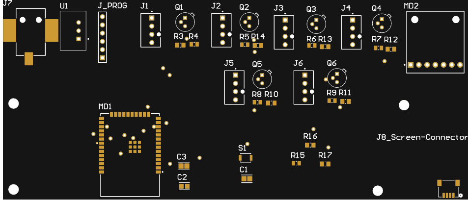
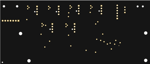
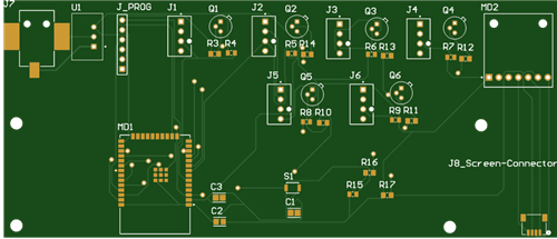
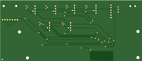
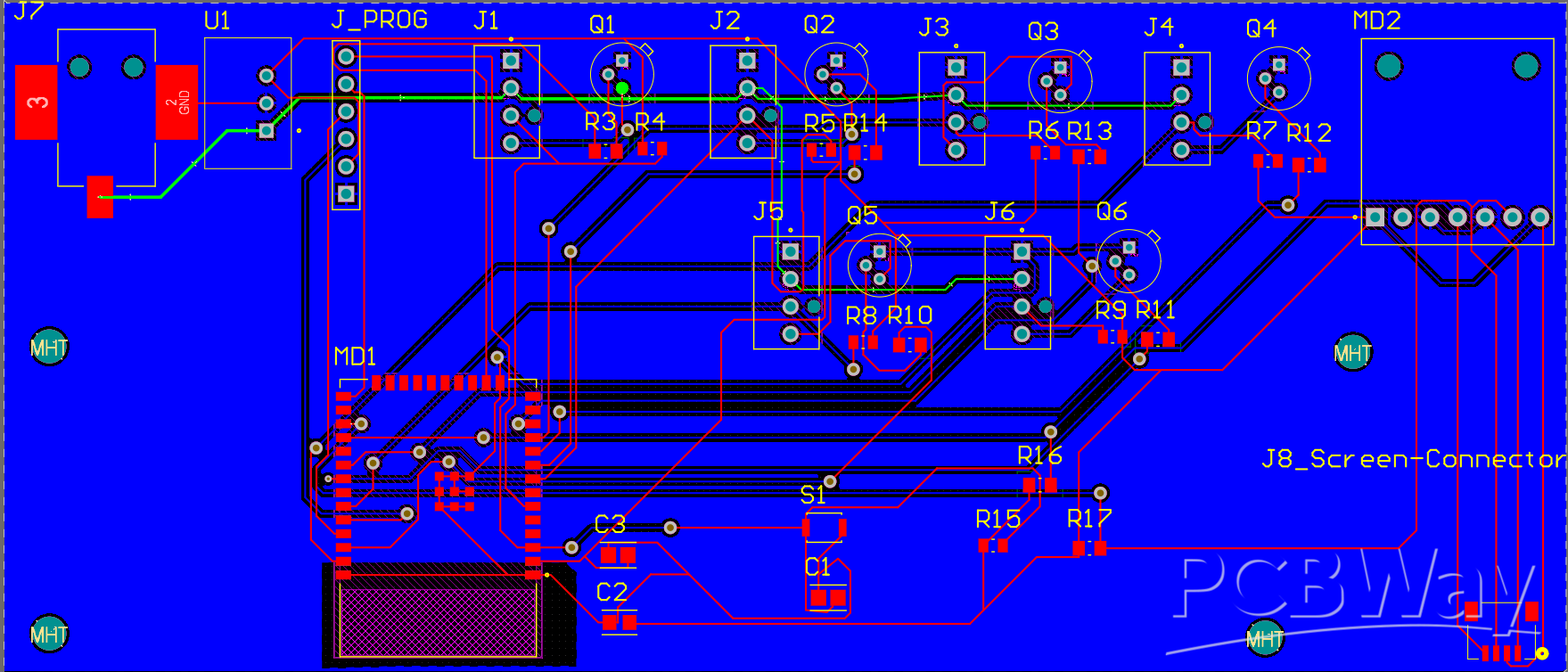
The PCB is designed around the ESP32-WROOM-32E and operates from a nominal 24 V supply.
The incoming 24 V rail directly supplies the connected fans, while a TRACO Power TSR 1-2433E switching regulator generates the 3.3 V rail required by the ESP32 and control electronics. The main hardware consists of the ESP32 module, six four-wire fan connectors, six PWM transistor stages, six tachometer inputs, the 3.3 V DC/DC power supply, BME280 environmental sensing, an I²C OLED connector and a UART programming/debug interface.
Fail-Safe Design
Since this board is responsible for cooling, several parts of the firmware are deliberately designed to fail toward maximum airflow rather than minimum airflow. Fan startup uses a full-speed boost, loss of temperature information during automatic control results in maximum cooling, firmware updates force the fans to full speed, and fan operation is verified using actual tachometer feedback wherever possible.
The intention is that a communication or software problem should not silently result in loss of cooling.
Summary
What started as a six-channel PWM fan controller developed into a complete ESP32-based thermal-management system.
The combination of independent RPM feedback, automatic per-fan calibration, temperature-based control, local OLED monitoring, Wi-Fi configuration, OTA updates and end-to-end diagnostics allows the controller to adapt to the fans connected to it rather than relying only on fixed PWM percentages.
It is designed primarily for applications requiring multiple 24 V PWM fans where reliable control, monitoring and easy configuration are more important than simply switching fans on and off.
ESP32 6-Channel 24V Smart PWM Fan Controller (WLAN/Bluetooth Ready)
Project images are for reference only. Actual production is based on the manufacturing files on the project page.
Please review the designer's notes (e.g., PCB thickness) and select the appropriate options.
PCBWay is not responsible
for issues caused by unsuitable parameter selections.
For more important ordering information, please refer to
Read More









Raspberry Pi 5 7 Inch Touch Screen IPS 1024x600 HD LCD HDMI-compatible Display for RPI 4B 3B+ OPI 5 AIDA64 PC Secondary Screen(Without Speaker)
BUY NOW


- Comments(0)
- Likes(1)
More by Timo Schweizer
-
Émetteur Récepteur Optique Expérimental (communication UART ATtiny + fibre optique)
117 0 1 -
SmallOLED - Live PC Stats, Animated Clocks & Audio Visualizer
941 0 3 -
"Talking Multimeter": Arduino-Based Speech Add-on for Multimeters with SCPI Protocol
547 0 1 -
Programmable Mist Maker - XIAO / QT PY Extension
3011 2 3 -
RadioHAT - Raspberry Pi radio development platform
2559 0 4 -
-
-