


Building a WiFi Filament Spool Scale with ESP32-C3 and HX711
Building a WiFi Filament Spool Scale with ESP32-C3 and HX711
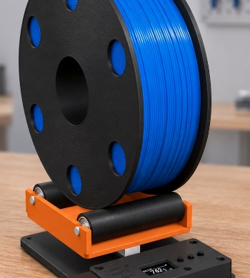
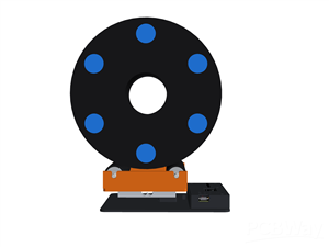
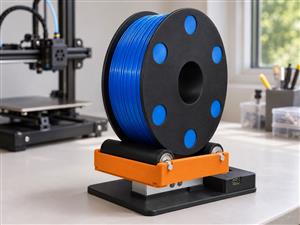
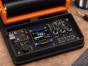
Design status: This is a complete open hardware design, but it has not yet been assembled or tested as a physical prototype. Product photographs are computer-generated visualizations based on the CAD; fit, load-cell readings and calibration remain to be checked on the first build.
Licensing
PCBWay’s project-level field is set to the site’s CC BY-SA default. The licenses by component are: hardware files under CERN-OHL-S-2.0, firmware under MIT, and 3D models under CC BY-NC-SA 4.0.
Why I built it
"Is there enough filament left on this spool for a 180 g print?" Every 3D printing maker has asked that question. Empty spool weights change from brand to brand, the label is gone after a few weeks and in the end you guess, start the print and hope.
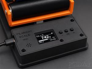
I wanted a spool holder that answers the question at a glance, warns me before the spool runs out in the middle of a long print and lets me check the numbers from my phone or from Home Assistant. The result is this roller spool holder with a 5 kg load cell under the cradle and a small custom PCB in the base: an ESP32-C3 SuperMini, an HX711 24-bit load cell ADC, a 0.96" OLED, three buttons and a buzzer. The spool is designed to roll on four 608 bearings while the printer pulls filament.
Features
• Filament left in grams, meters and percent (12 material presets, 1.75 / 2.85 mm)
• Low filament alarm with a buzzer, adjustable threshold, mute button
• Web dashboard for phone and PC plus a JSON API (/api/status) ready for Home Assistant
• WiFi setup portal with a random password shown on the OLED: no credentials in the code
• Empty spool tare with one button ("weigh empty spool") and two-step calibration with a known weight
• Designed to work while printing: the spool rolls on 4x 608 bearings
• Fits spools up to 92 mm wide, 100 to 300 mm in diameter, up to about 4.5 kg
• Custom 2-layer PCB with the HX711 analog front-end on board: no breakout boards, no loose wires
• 3D printed parts that print without supports, each one in a few hours
Specifications
Item: ValueMCU: ESP32-C3 SuperMini (RISC-V 160 MHz, WiFi 4, BLE 5, USB-C)Load cell ADC: HX711, 24 bit, channel A gain 128, 10 samples/sLoad cell: 5 kg straight bar, 80 x 12.7 x 12.7 mm (TAL220 type), 1.0 mV/VExcitation / analog supply: 4.00 V regulated on board (S8550 pass transistor)Display: 0.96" SSD1306 OLED, 128 x 64, I2CControls: 3 tact switches (- / OK / +)Alarm: MLT-8530 magnetic buzzer, 2.7 kHzPower: 5 V from USB-CDisplay resolution: 1 gPCB: 96 x 42 mm, 2 layers, 1.6 mm FR4, 4x M3 mounting holesScale footprint: 120 x 167 mm, rollers 92 mm long
How it works
Load cell and HX711. The load cell is a full Wheatstone bridge: four strain gauges glued on an aluminium bar. The HX711 excites the bridge with its analog supply (AVDD) and reads the differential output on channel A with a gain of 128. Because AVDD is also the ADC reference, the measurement is ratiometric: if the supply moves, the bridge output and the reference move together and the reading stays put.
A clean analog supply. The HX711 has an internal regulator that only needs an external PNP transistor. Q1 (S8550) takes the USB 5 V rail and R1/R2 set the output: AVDD = 1.25 V x (1 + R1/R2) = 1.25 x (1 + 22k / 10k) = 4.00 V. That leaves at least 0.4 V of headroom (the datasheet asks for 0.1 V) even on a weak USB port. The digital side of the HX711 (DVDD) runs at 3.3 V from the SuperMini, so DOUT and PD_SCK are 3.3 V logic: the ESP32-C3 pins are not 5 V tolerant.
Input filter. R3, R4 (100 R) and C6 (100 nF) form the RC filter of the HX711 reference design. Channel B is not used and its inputs are tied to ground. RATE and XI are grounded: 10 samples per second with the internal oscillator, the slowest and quietest mode.
Buzzer driver. GPIO7 drives the S8050 (Q2) through R5. R6 keeps the transistor off while the ESP32-C3 boots and D1 clamps the coil of the MLT-8530 magnetic buzzer.
Firmware filtering. Every HX711 sample goes through a 5-sample median filter (spikes) and an adaptive exponential filter: it follows a real change of weight within a few samples but smooths the noise when nothing happens. A reading is flagged as stable when the last second stays inside 2 g. When the cradle is empty, a slow zero tracking removes the drift of the load cell.
The PCB
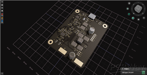
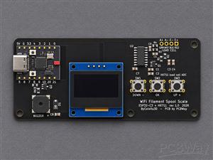
I designed the board in KiCad around the modules most makers already have in a drawer: the ESP32-C3 SuperMini and the 0.96" OLED. The HX711, its regulator and the buzzer driver are SMD parts on the board, so there are no breakout boards and no loose wires between the load cell and the microcontroller.
Design notes:
• Two-layer board with a ground pour on both sides and the analog section (HX711, R1-R4, C3-C6) grouped next to the load cell pads.
• No copper under the SuperMini antenna. The antenna end of the module points toward the OLED and the keep-out area is free of tracks and pour.
• Assembly-friendly silkscreen: exact outline of both modules, [ANTENNA THIS SIDE], [PIN 1 / GPIO5], USB-C position, the OLED pin order (GND VCC SCL SDA) and the color of every load cell wire.
• The SuperMini is soldered flat on the carrier (no header spacer) so the whole electronics fits under a lid that sits only 5.8 mm above the PCB.
• Production files ready for PCBWay: Gerbers, drill files, BOM with LCSC part numbers and a pick and place file with the origin at the bottom left corner. All SMD parts are on the top side.
The PCB is designed for manufacture by PCBWay: 96 x 42 mm, 2 layers, 1.6 mm thick, black solder mask and white silkscreen (any color works).
Bill of materials
PCB parts
Ref: Qty | Part | Package | LinkU1: 1 | ESP32-C3 SuperMini | module | AliExpressU2: 1 | HX711 | SOP-16 | LCSC C43656Q1: 1 | S8550 PNP | SOT-23 | LCSC C105432Q2: 1 | S8050 NPN | SOT-23 | LCSC C2146D1: 1 | 1N4148W | SOD-123 | LCSC C81598BZ1: 1 | MLT-8530 magnetic buzzer | SMD 8.5 mm | LCSC C94599R1: 1 | 22 k 1 % | 0805 | LCSC C17560R2, R6: 2 | 10 k 1 % | 0805 | LCSC C17414R3, R4: 2 | 100 R 1 % | 0805 | LCSC C17408R5: 1 | 1 k 1 % | 0805 | LCSC C17513C1, C3, C8: 3 | 10 uF 25 V X5R | 0805 | LCSC C15850C2, C4-C7: 5 | 100 nF 50 V X7R | 0805 | LCSC C49678SW1-SW3: 3 | Tact switch 6 x 6 mm, 10.5 mm tall | THT | LCSC C136677J2: 1 | 0.96" OLED SSD1306 I2C, 4 pins (GND VCC SCL SDA) | module | AliExpress
Mechanics
Qty: Part1: 5 kg straight bar load cell 80 x 12.7 x 12.7 mm (AliExpress)4: 608 bearings 8 x 22 x 7 mm2: M5 x 12 socket head screws (load cell to base, 14 mm maximum)2: M4 x 14 or x 16 countersunk screws (cradle to load cell)4: M3 x 16 countersunk screws (lid, PCB and base)4: 12 mm rubber feet (optional)
3D printed parts
Part: Qty | NotesBase: 1 | electronics bay, load cell pedestal, cable clipLid: 1 | 45-degree OLED window, printed top face downCradle: 1 | bolted to the load cell, 4 drop-in axle slotsRoller: 2 | a 608 bearing pressed into each endAxle: 2 | 8 mm core, 6 mm ends that drop into the slotsSpacer: 1 | 3 mm between the load cell and the cradle
PLA or PETG, 0.2 mm layers, 3 walls, 20 % gyroid infill, no supports (axles and spacer at 100 % infill). Every part fits a 180 x 180 mm bed. The STL, 3MF and STEP files are attached to this project.
Assembly
1. Solder the PCB
• SMD parts first (or order the board assembled by PCBWay with the BOM and CPL files). The HX711 pin 1 dot goes next to Q1, the D1 cathode band matches the bar on the silkscreen and the buzzer "+" pad is marked.
• Tact switches.
• OLED: check that your module reads GND VCC SCL SDA from left to right (some modules swap GND and VCC) and solder it with its own header.
• ESP32-C3 SuperMini, flat on the board: component side up, USB-C over the left edge, antenna toward the OLED. Push single pins out of a 2.54 mm header strip, put one pin through each pair of holes, solder both sides and trim them under the board. Castellated SuperMini boards can be soldered directly.
2. Build the mechanics
• Screw the load cell on the pedestal of the base with 2x M5 x 12 from below. The cable end goes toward the electronics bay and the arrow on the load cell points down.
• Put the spacer on the free end and fix the cradle with 2x M4 countersunk screws. The cradle only touches the load cell: there are 5 mm of air between the cradle and the base.
• Press two bearings into each roller, slide the rollers onto the axles and drop them into the slots.
3. Wire the load cell and close the lid
• Pass the 4 wires under the clip and through the slot of the electronics bay.
• Place the PCB on the 4 bosses (USB-C in the notch) and solder the wires: E+ red, E- black, A- white, A+ green.
• Close the lid with 4x M3 x 16 countersunk screws: they go through the lid and the PCB into the bosses.
Firmware
The firmware is written with the Arduino core for the ESP32 (3.x) and builds both in the Arduino IDE and in PlatformIO. It only needs the Adafruit SSD1306 and GFX libraries; the HX711 driver, the web server and the WiFi portal are part of the code.
Arduino IDE: install esp32 by Espressif (3.x) and Adafruit SSD1306, select the board Nologo ESP32C3 Super Mini, open WifiFilamentScale.ino and upload.PlatformIO: pio run -t upload in the 03_firmware folder.No toolchain: flash wifi_filament_scale_v1.0.0_merged_0x0.bin at address 0x0 with Espressif's web flasher (https://espressif.github.io/esptool-js/).
First boot and calibration
• Power the scale with the cradle empty: the first boot zeroes it automatically.
• Hold OK to open the menu, choose Calibrate, remove everything, press OK, put a known weight on the cradle, set its value with - / + and press OK.
• Set the material, the diameter, the empty spool weight (or use Weigh empty spool with an empty spool of the same brand) and the filament weight of a new spool. Done.
On the main screen - and + switch the big number between grams, meters and percent. OK shows the IP address. When the low filament alarm beeps, OK mutes it until a fuller spool is loaded.
WiFi, web dashboard and Home Assistant
Menu, WiFi setup: the scale reboots as an access point and the OLED shows its name and a random 8-digit password. Join it with your phone, open http://192.168.4.1, pick your network and save. After the reboot the dashboard is at http://filamentscale.local.
Home Assistant reads /api/status with the REST integration:
rest:
- resource: http://filamentscale.local/api/status
scan_interval: 30
sensor:
- name: "Filament remaining"
value_template: "{{ [value_json.filament_g, 0] | max | round(0) }}"
unit_of_measurement: "g"
- name: "Filament length"
value_template: "{{ value_json.meters | round(1) }}"
unit_of_measurement: "m"
binary_sensor:
- name: "Filament low"
value_template: "{{ value_json.low }}"
Tips
• Weak WiFi? Many SuperMini boards have a badly tuned antenna. The firmware lowers the TX power to 8.5 dBm, the known fix; raise it in config.h if your board connects well.
• Most precise reading: look at it when the printer is idle. While printing, the filament tension adds or removes a few grams depending on the filament path.
• Negative weight when loading? A+ and A- are swapped. Swap them or just calibrate: the sign is stored.
• Do not lean on the cradle: the 5 kg load cell survives 120 % of its capacity, not a hand pushing down.
Files
• Gerber files, BOM (with LCSC part numbers) and pick and place file
• Schematic (PDF) and complete KiCad 10 project
• Firmware source (Arduino / PlatformIO) and ready-to-flash binary
• 3D printed parts: STL, 3MF and STEP
PCB fabrication
The PCB fabrication files are included with this project, so the board can be ordered directly from PCBWay, bare or fully assembled with PCBWay's assembly service (the BOM and pick and place files are attached).
Building a WiFi Filament Spool Scale with ESP32-C3 and HX711
Project images are for reference only. Actual production is based on the manufacturing files on the project page.
Please review the designer's notes (e.g., PCB thickness) and select the appropriate options.
PCBWay is not responsible
for issues caused by unsuitable parameter selections.
For more important ordering information, please refer to
Read More


Raspberry Pi 5 7 Inch Touch Screen IPS 1024x600 HD LCD HDMI-compatible Display for RPI 4B 3B+ OPI 5 AIDA64 PC Secondary Screen(Without Speaker)
BUY NOW

- Comments(0)
- Likes(1)
More by Inaki Iturriaga
-
 Battery-Powered ESP32-CAM Continuous Video Recorder
OverviewThis project transforms an ESP32-CAM module into a standalone, battery-powered video recordi...
-
 GPS Mobile Beacon
Building a GPS Emergency Beacon: A DIY TutorialWelcome to our latest DIY project: creating a GPS Eme...
-
 Wireless RFID Card Copier.
Wireless RFID Card CopierIn today's digital world, security and accessibility are of paramount impor...
-
 Piezo Alert System.
Within the fast-evolving sphere of security tools and home automation, creativity often paves the wa...
-
 Wifi Weather Station - Sensors board
WiFi Weather Station - Sensor unitIn our digital era, many electronics projects integrate diverse se...
-
 Building a WiFi Filament Spool Scale with ESP32-C3 and HX711
Design status: This is a complete open h...
-
 Building a GPS Speedometer with RP2040-Zero
Build a Feature-Packed GPS Speedometer with an RP2040This project guide will walk you through buildi...
-
 RC Receiver
Build Your Own RC ReceiverHarnessing advanced electronics and precise control systems, the RC Receiv...
-
 Universal RC Controller
Build Your Own Universal RC RemoteHarnessing the power of custom PCBs and wireless communication, th...
-
 Continuous GPS Tracker
This compact and efficient tracker provides real-time location updates, making it ideal for surveill...
-
 Air Quality Monitor
Welcome to our DIY tutorial on assembling an Air Quality Monitoring Device. This project is perfect ...
-
 Automatic Watch Winder
In the realm of luxury timepieces and watch aficionados, an automatic watch is...
-
 Handheld GPS
Within the swiftly advancing realm of portable technology and travel essentials, innovation often sh...
-
 Dual Motor Controller for Model Robotics
In the thrilling world of robotics and DIY engineering, innovation continues to soar to new heights....
-
 Altitude Indicator with Beeper for Rocketry
Altitude Indicator for Model RocketryIn our ever-advancing technological landscape, countless projec...
-
 Wifi Weather Station - Display unit
WiFi Weather Station - Display UnitIn this technologically advanced age, countless electronics proje...
-
 Positon Breakout Board
Position Sensors Breakout Board In today's era of advanced technology, many electronics projects req...
-
 Ambient Sensors Breakout Board
In today's world, electronics projects often require the integration of multiple sensors to collect ...
-
-
-
AudioLink – USB & Bluetooth LE Audio / Auracast Receiver with Balanced Line Outputs (nRF5340)
271 0 0 -
-
-
-
Émetteur Récepteur Optique Expérimental (communication UART ATtiny + fibre optique)
357 0 1 -
SmallOLED - Live PC Stats, Animated Clocks & Audio Visualizer
1418 0 3 -
"Talking Multimeter": Arduino-Based Speech Add-on for Multimeters with SCPI Protocol
795 0 1