Antenna (or whatever) Selector SHIELD for Arduino Uno
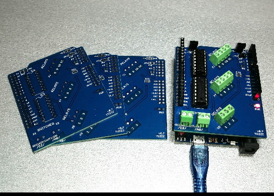
This shield was designed with no particular project in mind. It aims to be useful for both automatic and keypad-operated antenna selectors in general. This is just hardware, providing slightly more than a set of ten relay drivers, but there are many projects/sketches on the Internet (including my blog) that could be easily adapted to work with it. The shield could also help build other Arduino-based devices that will switch multiple loads on and off and may have nothing to do with amateur radio.
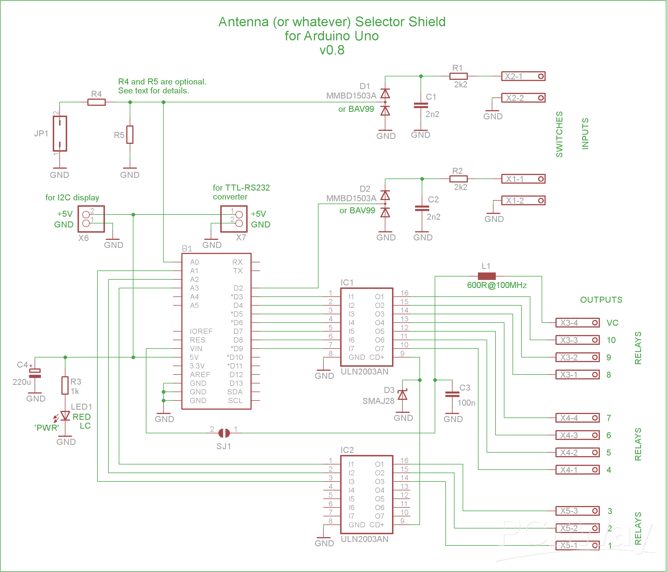
The ULN2003 IC is an array of seven low-side Darlington-pair drivers. On this shield there are ten available drivers in total and they can be controlled by Arduino. So there can be ten antenna-switching relays. Each relay coil should be connected between a driver (‘OUT’ in the picture) and the positive power rail, and the driver conducts current to GND when turned on. The introduced voltage drop can be up to 1V, which by itself shouldn’t present a problem for 12V relays. Check the relays datasheet anyway.
The way the power is supplied is important: if the project requires an LC display with a backlight and some other peripheral devices each drawing 50 or 100 mA on +5V – the Arduino Uno and the shield(s) should be supplied with +5V from an external and sufficiently powerful source through the USB connector on the Arduino Uno. In this scenario, the common positive voltage for the relay coils will generally come from a separate source (+24V max) that shares a common ground with the Arduino board. DO NOT bridge the SMD jumper SJ1.
On the other hand, if the total power consumption is low, the Arduino Uno and the attached devices can be powered from the 5V regulator on the Arduino board, i.e by connecting 9…12V to Vin. In that case, provided that you use appropriate relays, you can bridge the SMD jumper SJ1 and then use the voltage from the VC (Voltage Common) contact to power the relays. It’s “Voltage Common” because it’s common for all the relays. VC will basically be the same as Vin of the board, only a simple RF filter in between to protect Vin from possible RF noise collected by a long VC wire.
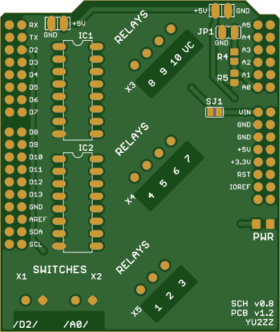
There are two inputs intended for simple switches (at D2 and A0), as well as a jumper at A0, because someone may just need a jumper instead of the second switch. These inputs at D2 and A0 are adequately protected against overvoltage, reverse polarity and RFI. When a switch is closed, the respective pin is at GND.
The UART, I2C and SPI pins of the uCU are all available for either their specific functions or for use as general I/O pins.
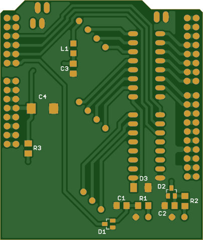
On this shield there are two parallel rows of holes/pads along each side so it is in principle possible to use ‘normal’ male pin headers on the bottom side and ‘normal’ female ones on the top. But, with ‘stacking headers’ and their extra-long pins, the outer rows of holes/pads are left available for soldering connections, which is quite convenient. Stacking headers also provide more clearance between the boards.
A0 can be used in multiple ways (one at a time) – which is in principle true for any Arduino pin – but here A0 is specifically intended for multiple usage scenarios:
Only if you need to use A0 as an analog input for, say, the Icom ‘Band Voltage’, both R4 and R5 will be needed, and their values will be critical, as they will form the necessary voltage divider at the input. Also it would be good to add a 10-100 nF capacitor in parallel to R5. The jumper (JP1) pins will be used as input terminals for the ‘Band Voltage’.
Otherwise:
If you don’t need the jumper JP1 at A0, leave the two pins of JP1 unconnected. R4 and R5 are irrelevant and you don’t need them.
If you intend to use jumper JP1, install R4 with a value of 0Ω or some other low value, or just bridge the gap between the R4 pads with solder. Leave the place for R5 empty.
And, obviously, if you and your program use the protected switch input at A0, you can’t use A0 for anything else. So leave the two pins of JP1 unconnected. Also, in that case, R5 must be removed and R4 is irrelevant.
Finally, you can choose to access and use both D2 and A0 directly, bypassing or omitting the protection circuits altogether.
Important: Antenna selectors should be housed in grounded metal enclosures and completely disconnected during stormy weather.
Notes regarding the schematic:
– If the VC contact is not used, L1 and C3 can be omitted. If L1 is replaced by a resistor, the value of this resistor (R) should be very low, 0 ohms to 5 ohms. This will limit the voltage drop across the resistor, which is equal to the relay coil current times R.
– If all the relay coils are fitted with flyback diodes, D3 could be omitted.
– C4 (size D tantalum) is more useful or needed if the load on the +5V power rail is high or ADC is used.
– In fact, pretty much anything could be omitted or adjusted for the specific design – provided that you know what you’re doing.
Please also read the full article:
https://yu2zz.com/2025/12/29/antenna-or-whatever-selector-shield-for-arduino-uno/
Antenna (or whatever) Selector SHIELD for Arduino Uno
Project images are for reference only. Actual production is based on the manufacturing files on the project page.
Please review the designer's notes (e.g., PCB thickness) and select the appropriate options.
PCBWay is not responsible
for issues caused by unsuitable parameter selections.
For more important ordering information, please refer to
Read More









Raspberry Pi 5 7 Inch Touch Screen IPS 1024x600 HD LCD HDMI-compatible Display for RPI 4B 3B+ OPI 5 AIDA64 PC Secondary Screen(Without Speaker)
BUY NOW


- Comments(1)
- Likes(1)
More by Mire YU2ZZ
-
 "Talking Multimeter": Arduino-Based Speech Add-on for Multimeters with SCPI Protocol
This project uses the SCPI communication protocol, which is supported by many modern measurement and...
"Talking Multimeter": Arduino-Based Speech Add-on for Multimeters with SCPI Protocol
This project uses the SCPI communication protocol, which is supported by many modern measurement and...
-
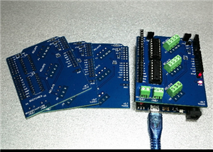 Antenna (or whatever) Selector SHIELD for Arduino Uno
This shield was designed with no particular project in mind. It aims to be useful for both automatic...
Antenna (or whatever) Selector SHIELD for Arduino Uno
This shield was designed with no particular project in mind. It aims to be useful for both automatic...
-
 USB CW Keying Interface
The interface has been successfully tested with Win-Test and DXLog under Windows 10 and Windows 7 (b...
USB CW Keying Interface
The interface has been successfully tested with Win-Test and DXLog under Windows 10 and Windows 7 (b...
-
 ‘PIC-Keyer’: 2025 Edition
This is a Morse keyer by DL4YHF, who designed the circuit and wrote the software 26 years ago. I jus...
‘PIC-Keyer’: 2025 Edition
This is a Morse keyer by DL4YHF, who designed the circuit and wrote the software 26 years ago. I jus...
-
 Simple but Smart Radio Direction Finding for VHF and UHF ‘Fox Hunting’
A diode will conduct RF only if it is forward-biased; that is why it can be used as a DC-controlled ...
Simple but Smart Radio Direction Finding for VHF and UHF ‘Fox Hunting’
A diode will conduct RF only if it is forward-biased; that is why it can be used as a DC-controlled ...
-
 Arduino-Based DSP Morse Decoder and Trainer
This real-time Morse decoder and trainer uses the Goertzel algorithm to detect a CW tone of 708 Hz. ...
Arduino-Based DSP Morse Decoder and Trainer
This real-time Morse decoder and trainer uses the Goertzel algorithm to detect a CW tone of 708 Hz. ...
-
Programmable Mist Maker - XIAO / QT PY Extension
2158 2 2 -
RadioHAT - Raspberry Pi radio development platform
1836 0 4 -
-
-
-
ARPS-2 – Arduino-Compatible Robot Project Shield for Arduino UNO
4040 0 6 -
A Compact Charging Breakout Board For Waveshare ESP32-C3
4780 3 8 -
AI-driven LoRa & LLM-enabled Kiosk & Food Delivery System
5596 2 2 -