|
|
SM04B-SRSS-TB(LF)(SN)JST Sales America
|
x 2 | |
|
|
LTST-C170KSKTLITE-ON
|
x 1 | |
|
|
RC0805FR-071KLYageo
|
x 1 | |
|
|
RC0805FR-074K7LYageo
|
x 2 |
|
|
KiCad 10KiCad
|
Adapt-2-QWIIC
Lately, I've been playing with a number of interesting and inexpensive I2C modules purchased online. Almost all of them have pads to mount a 2.54mm header – but I wanted an easier way to connect them to the QWIIC socket on my BEAPER Nano and BEAPER Pico circuits.
Unfortunately, not all of the header pin layouts on these circuits are the same. Most of the circuits I have on hand have one of two, common, pin-outs. I designed Adapt-2-QWIIC to adapt both of these two styles to QWIIC connectors.
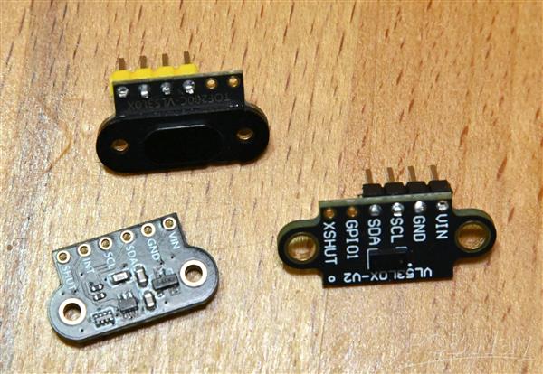
Photo: Two different VL53L0X ToF (Time-of-Flight) distance sensor modules. Left are the front (top) and back (bottom) of one style of module, at the right is a second style of module. The second module has its VIN and GND pins at the opposite side of the header, compared with the first module, when both are viewed from the front.
What's QWIIC?
QWIIC is a 4-pin polarized connector ecosystem developed by Sparkfun to connect 3.3V I2C peripheral devices to microcontroller boards. It's one of a number of different interconnection systems, and this page on the Adafruit website has a good comparison of the most common interconnects.
The main features of QWIIC are: the use of a 1mm-pitch, 4-pin JST-SH connector and cable, and 3.3V operation for both power and I2C signals. Since I2C is a shared bus, QWIIC devices often include two connectors, to enable devices to be connected in a daisy-chain from one to the next.
Adapt-2-QWIIC
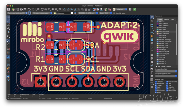
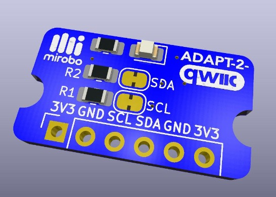
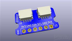
Photo: Screen shot of the Adapt-2-QWIIC layout in KiCad showing the pin header connections (bottom) and cuttable jumpers beside the R1 and R2 SCL and SDA pull-up resistors. At the top is a power LED and current-limiting resistor. The JST SH QWIIC connectors are on the back side.
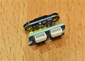
In its simplest form, Adapt-2-QWIIC connects one or two JST SH QWIIC connectors to 2.54mm header pins.
Most I2C hosts and many I2C peripherals already include the appropriate I2C bus SCL and SDA pull-up resistors. Adapt-2-QWIIC provides two sets of 0805 SMD pads to let you add pull-up resistors if none of the other I2C bus devices contain their own. If, after mounting pull-up resistors on Adapt-2-QWIIC you find they're no longer needed, two cuttable jumpers lets you quickly disable them without any desoldering.
In the remaining bit of space left on the board, I also added pads for an 0805 LED as a power indicator and its current-limiting resistor – an unnecessary but nice-to-have addition to verify a device is (or should be) powered.
Building Adapt-2-QWIIC
While soldering SMD components is challenging, the use of 0805 components means it's easily manually accomplished with a fine-tipped soldering iron. For the JST-SH connectors, I find using a solder paste stencil and hot air or a hot plate for soldering easier – even if it takes a bit more time than manually soldering the pins. Since the main purpose of Adapt-2-QWIIC is providing QWIIC connectors, solder these onto the PCB first. Adding these first makes it easier to keep the board flat on a hot plate before adding the other components on the opposite side.
If your device needs pull-up resistors, add these next. 4.7kΩ is the usual common I2C pull-up value, but some higher-speed I2C circuits benefit from lower values such as 2.2kΩ resistors instead. But, it's important to know how many other devices on the I2C bus also include pull-ups, and their values to determine the best value of pull-up resistors to use.
If you'd like to include a power indicator, add an 0805 LED and current-limiting resistor. I've specified a 1kΩ resistor to minimize LED current in the schematic, but you can reduce its value if you want the LED to be brighter.
For most applications, you'll likely add a 4-pin header or header socket either at one end or the other end of the 6 through-hole pads in the board. Choose the position that matches the signals on your I2C device. I use a header socket on Adapt-2-QWIIC and matching header pins on the device for easy interchangeability. For a permanent connection with a lower profile and a smaller gap between the circuit boards, solder header pins directly into each circuit.
You can find a complete list of parts for Adapt-2-QWIIC shared on DigiKey.
Adapt-2-QWIIC is a simple circuit, and I hope it can be a useful addition to your hobby circuits bin!
Adapt-2-QWIIC
Project images are for reference only. Actual production is based on the manufacturing files on the project page.
Please review the designer's notes (e.g., PCB thickness) and select the appropriate options.
PCBWay is not responsible
for issues caused by unsuitable parameter selections.
For more important ordering information, please refer to
Read More









Raspberry Pi 5 7 Inch Touch Screen IPS 1024x600 HD LCD HDMI-compatible Display for RPI 4B 3B+ OPI 5 AIDA64 PC Secondary Screen(Without Speaker)
BUY NOW


- Comments(0)
- Likes(0)
More by John Rampelt
-
 QWIIC-VL53L4CD Time-of-Flight Distance Sensor Module
The good old HC-SR04 SONAR module, and its newer, 3.3V HC-SR04P sibling, have long been go-to distan...
QWIIC-VL53L4CD Time-of-Flight Distance Sensor Module
The good old HC-SR04 SONAR module, and its newer, 3.3V HC-SR04P sibling, have long been go-to distan...
-
 ARPS-2 – Arduino-Compatible Robot Project Shield for Arduino UNO
Meet ARPS-2ARPS-2 is version two of my Arduino-compatible Robot Project Shield for Arduino UNO. ARPS...
ARPS-2 – Arduino-Compatible Robot Project Shield for Arduino UNO
Meet ARPS-2ARPS-2 is version two of my Arduino-compatible Robot Project Shield for Arduino UNO. ARPS...
-
 BEAPER Pico 0.1: A (Prototype) Beginner Electronics and Programming Educational Robot for Raspberry Pi Pico
BackgroundI have been teaching high school electronics and computer technology courses for over thir...
BEAPER Pico 0.1: A (Prototype) Beginner Electronics and Programming Educational Robot for Raspberry Pi Pico
BackgroundI have been teaching high school electronics and computer technology courses for over thir...
-
 CHRP4 Beginner Robotics Developer Board
CHRP4 OverviewCHRP4 (Common Hardware Robotics Project - version 4) is beginner-friendly microcontrol...
CHRP4 Beginner Robotics Developer Board
CHRP4 OverviewCHRP4 (Common Hardware Robotics Project - version 4) is beginner-friendly microcontrol...
-
 Adapt-2-QWIIC
Lately, I've been playing with a number of interesting and inexpensive I2C modules purchased online....
Adapt-2-QWIIC
Lately, I've been playing with a number of interesting and inexpensive I2C modules purchased online....
-
 BEAPER Nano V1.01 – Beginner Electronics and Programming Educational Robot for Arduino Nano ESP32
BEAPER Nano built as a simple obstacle-sensing robot using left and right optical floor sensor modul...
BEAPER Nano V1.01 – Beginner Electronics and Programming Educational Robot for Arduino Nano ESP32
BEAPER Nano built as a simple obstacle-sensing robot using left and right optical floor sensor modul...
-
 BEAPER Pico v1.00 – Beginner Electronics and Programming Educational Robot for Raspberry Pi Pico and Pico 2
Meet BEAPER PicoBEAPER stands for Beginner Electronics and Programming Educational Robot, and Pico r...
BEAPER Pico v1.00 – Beginner Electronics and Programming Educational Robot for Raspberry Pi Pico and Pico 2
Meet BEAPER PicoBEAPER stands for Beginner Electronics and Programming Educational Robot, and Pico r...
-
 BEAPER Bot Robot Chassis
BEAPER BotBEAPER (Beginner Electronics and Programming Educational Robot) Bot is a 3D-printable BEAP...
BEAPER Bot Robot Chassis
BEAPER BotBEAPER (Beginner Electronics and Programming Educational Robot) Bot is a 3D-printable BEAP...
-
 BEAPER Nano 1.0: the Beginner Electronics and Programming Educational Robot circuit for Arduino Nano ESP32
When the Arduino Nano ESP32 was released with a combination of a fast, powerful microcontroller, lot...
BEAPER Nano 1.0: the Beginner Electronics and Programming Educational Robot circuit for Arduino Nano ESP32
When the Arduino Nano ESP32 was released with a combination of a fast, powerful microcontroller, lot...
-
 BEAPER Nano (Beginner Electronics and Programming Educational Robot) for Arduino Nano ESP32
Note: This is the first prototype BEAPER Nano circuit. See the newest BEAPER Nano 1.0 circuit. BEAPE...
BEAPER Nano (Beginner Electronics and Programming Educational Robot) for Arduino Nano ESP32
Note: This is the first prototype BEAPER Nano circuit. See the newest BEAPER Nano 1.0 circuit. BEAPE...
-
 BPStick (Breadboard Power Stick) - 5V through hole version
When schools start teaching STEM programs, or hobbyists embark on learning electronics, one of their...
BPStick (Breadboard Power Stick) - 5V through hole version
When schools start teaching STEM programs, or hobbyists embark on learning electronics, one of their...
-
 UPS (USB Power Stick) breadboard power adapter
When schools start teaching STEM programs, or hobbyists embark on learning electronics, one of their...
UPS (USB Power Stick) breadboard power adapter
When schools start teaching STEM programs, or hobbyists embark on learning electronics, one of their...
-
 ARPS – A Beginner Arduino®-compatible Robot Project Shield
ARPS OverviewARPS (Arduino®-compatible Robot Project Shield) is beginner-friendly add-on shield for ...
ARPS – A Beginner Arduino®-compatible Robot Project Shield
ARPS OverviewARPS (Arduino®-compatible Robot Project Shield) is beginner-friendly add-on shield for ...
-
 UBMP4 Beginner Microcontroller Development Board
UBMP4 OverviewUBMP4 (USB-based Beginner Multipurpose Project - version 4) is beginner-friendly micro...
UBMP4 Beginner Microcontroller Development Board
UBMP4 OverviewUBMP4 (USB-based Beginner Multipurpose Project - version 4) is beginner-friendly micro...
-
Émetteur Récepteur Optique Expérimental (communication UART ATtiny + fibre optique)
138 0 1 -
SmallOLED - Live PC Stats, Animated Clocks & Audio Visualizer
979 0 3 -
"Talking Multimeter": Arduino-Based Speech Add-on for Multimeters with SCPI Protocol
561 0 1 -
Programmable Mist Maker - XIAO / QT PY Extension
3032 2 3 -
RadioHAT - Raspberry Pi radio development platform
2581 0 4 -
-
-