


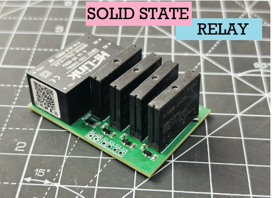
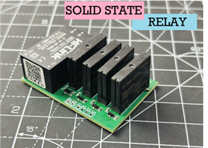
4 Channel SOLID STATE RELAY Module
I have designed a triac and optocoupler based project in the past, in which triac act as a relay and optocoupler as a controller. And works on the phenomena of zero crossing. Here is the . But today I want to make a relay module which can fit into a small housing space and I don’t want that clicking noise anymore of standard relays. Then what is the issue with the last project, where I am using standalone integrated circuits which have a limit of handling current. Today in this project we have G3MB, which is a solid state relay module, widely adapted for its performance. I want to merge this project with my ESP8266 offline voice controlled hub based on ESPNOW.
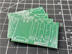
To implement this in a small form factor, I have designed a PCB. This project is sponsored by PCBWAY, I am really excited to see my PCBs in my hands after they are manufactured, they are perfect. No issues with design and I am using the PCBWAY services for a long time. You can consider PCBWAY for your project if it contains a PCB, use this link and get best prices on your first order.
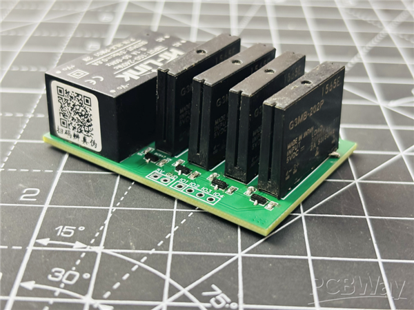
G3MB Relay Module:
Low cost Subminiature PCB mounting 2 amp Single in-line package (SIP). Bottom is approximately 3 times smaller than G3M. Low cost “SIP” package switches up to 2A loads. Built in Snubber circuit and input resistor as option.
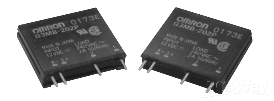
- Two footprints available for design flexibility.
- The G3MB-202PEG-4-DC20MA crosses directly to the Motorola M0C2A-60 series power triac.
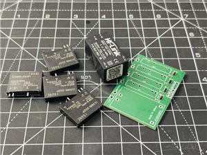
Components Required:
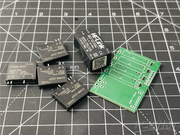
SSR G3MB
10k 0603 Resistor
BC847 SMT Transistor
Hi-Link Power supply 220V to 5V
SSR PCBs from PCBWAY
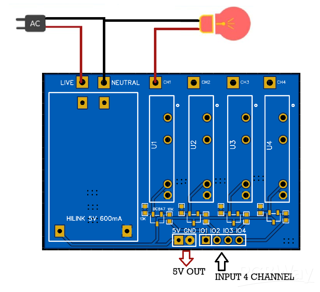
Circuit Diagram:
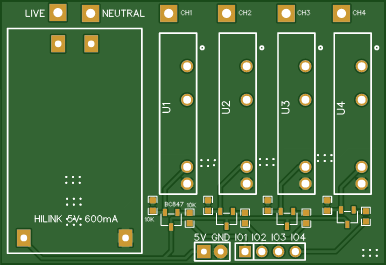
The circuit diagram is quite simple, we have a power conversion unit onboard which helps in switching of these relays. And to make them controllable through a single pin we have transistor drivers, the base is pulled low with the help of 10K resistors. The circuit does not have any capacitor but you can add one between the 5v and GND power line. I used the SMT parts to make it look cleaner as seen in the PCB below.
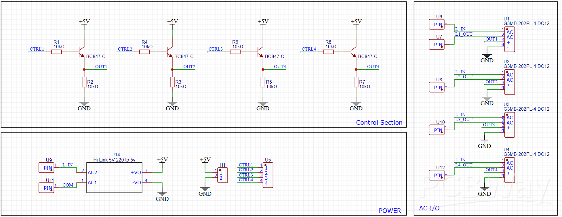
Coming to the relay part they have 4 pins, 2 for the DC 5v power controlled through transistor and headers. And two for AC, here we have to understand when the control signal is given the transistor makes the relay to switch and the relay will short the internal AC pins together to make the flow electric current through them. The application circuit diagram is given below, do the same to turn on/off the load devices. One more thing these relays are based on triac operation, so we can not apply DC to the AC pins, it will alter the operation of the device and can cause burn issues.
PCB Design:
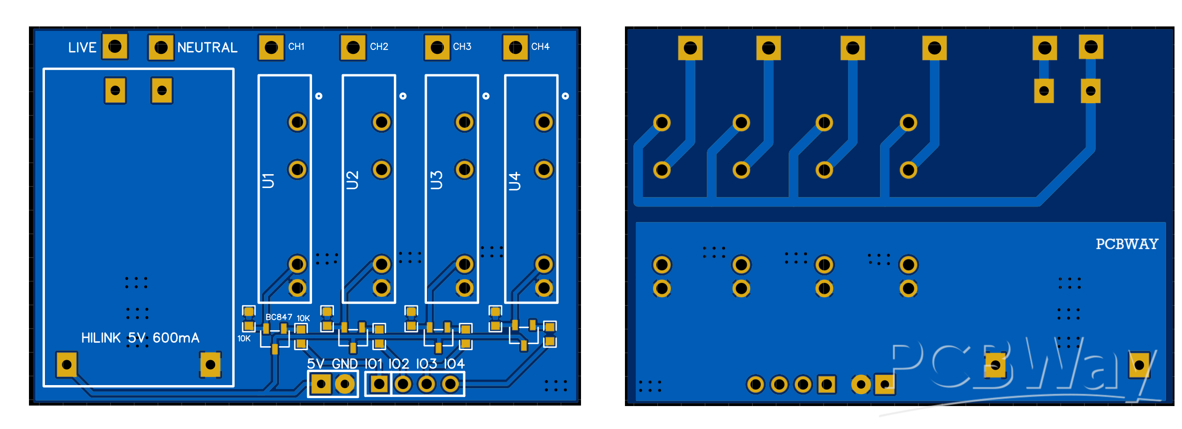
I have a choice to make it smaller by heading some relay to the backside, But I choose form factor over PCB miniaturisation. The PCB is quite well populated because the hi-link power supply takes more space. I organised everything on the top layer. The PCB only has two layers, some stitching vias for proper current flow, the above layer has a copper pour as ground and the bottom layer is half copper poured as can be seen in the picture above. I do not want to make copper expose stuff here, so I increase the thickness of the AC side PCB and to make it more good remove the ac side copper pour, all the AC traces at bottom and control traces on both the layers.
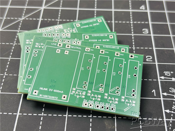
PCBWAY is the manufacturer here, I got the PCB exactly the same quality I supposed to be. PCBWAY is the one stop solution for all prototyping requirements, So what do they offer? PCBs, Stencil, CNC, PCBA, 3D Printing, Metal Parts, YES TO ALL! Explore now and get free coupons.
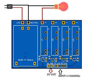
Application Circuit:
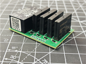
Here I have shared the one picture of the load device, it has 4 channels so 4 different devices can be operated from the 4 different pins. The controller can be a wire, microcontroller or manual. One line of the AC power directly goes to the load device and the second line through relay.
When operated it shorts the internal connection, completes the circuit and current flows. Really simple to assume and here is the test.
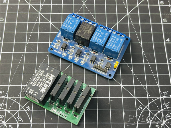
Testing and Working:
First give power to the HI-link supply and test if the 5v is coming or not. If everything is okay, make the other connections and then connect the headers to either MCU or manual triggering.
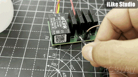
I am using a wire here which I will replace later with my Offline voice controller module and put everything in a box. It is working fine, the circuit is okay and the PCB is perfect. You can make your own all the files listed above. Thanks to PCBWAY!
4 Channel SOLID STATE RELAY Module
*PCBWay community is a sharing platform. We are not responsible for any design issues and parameter issues (board thickness, surface finish, etc.) you choose.


Raspberry Pi 5 7 Inch Touch Screen IPS 1024x600 HD LCD HDMI-compatible Display for RPI 4B 3B+ OPI 5 AIDA64 PC Secondary Screen(Without Speaker)
BUY NOW


- Comments(0)
- Likes(3)
 More by Engineer
-
 DIY a Smart NiMH/NiCd Battery Charger
When talking about standalone single cell battery chargers only one popular name came into my mind t...
DIY a Smart NiMH/NiCd Battery Charger
When talking about standalone single cell battery chargers only one popular name came into my mind t...
-
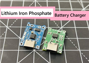 LiFePO4 Battery Charger With Protection
In the previous few months I tried to cover almost all types of battery charging integrated circuits...
LiFePO4 Battery Charger With Protection
In the previous few months I tried to cover almost all types of battery charging integrated circuits...
-
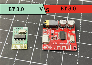 Comparison of Audio Bluetooth 3.0 and 5.0
Coming to bluetooth in audio applications, we have versions from 3.0 to 5.4. In the practical audio ...
Comparison of Audio Bluetooth 3.0 and 5.0
Coming to bluetooth in audio applications, we have versions from 3.0 to 5.4. In the practical audio ...
-
 4 Channel SOLID STATE RELAY Module
I have designed a triac and optocoupler based project in the past, in which triac act as a relay and...
4 Channel SOLID STATE RELAY Module
I have designed a triac and optocoupler based project in the past, in which triac act as a relay and...
-
 A Look at Capacitive Water Overflow Sensor
Detection of Water overflow in a tank is one of the main topics when it comes to energy saving appli...
A Look at Capacitive Water Overflow Sensor
Detection of Water overflow in a tank is one of the main topics when it comes to energy saving appli...
-
 Offline Voice Recognition Hub Based on ESPNOW
An offline voice recognition hub, no internet connection, no wifi router. Just a pair of ESP8266 wit...
Offline Voice Recognition Hub Based on ESPNOW
An offline voice recognition hub, no internet connection, no wifi router. Just a pair of ESP8266 wit...
-
 DIY a 200W Precise Electronic Load
Whenever I want to test some USB power supplies, drawing I-V characters of a power supply and workin...
DIY a 200W Precise Electronic Load
Whenever I want to test some USB power supplies, drawing I-V characters of a power supply and workin...
-
 Smallest 220V to 5V Supply for IOT applications
The requirement of stable DC power supplies in the IOT applications and in electronics designed prod...
Smallest 220V to 5V Supply for IOT applications
The requirement of stable DC power supplies in the IOT applications and in electronics designed prod...
-
 I made 200Watt Class D amplifier
I have designed this 200W Class D amplifier board, which is separated into 100+100 Watt stereo chann...
I made 200Watt Class D amplifier
I have designed this 200W Class D amplifier board, which is separated into 100+100 Watt stereo chann...
-
 iPAD Pencil Backup Pocket Charger
I have a clone iPAD pencil which works in the similar way of Apple pencil, but this one comes with C...
iPAD Pencil Backup Pocket Charger
I have a clone iPAD pencil which works in the similar way of Apple pencil, but this one comes with C...
-
 Digital Radio Transmitter and Receiver 433Mhz
Radio technology is the best monitoring and control solution for small and long range wireless hobby...
Digital Radio Transmitter and Receiver 433Mhz
Radio technology is the best monitoring and control solution for small and long range wireless hobby...
-
Programmable Mist Maker - XIAO / QT PY Extension
185 0 0 -
RadioHAT - Raspberry Pi radio development platform
202 0 1 -
-
-
-
-
ARPS-2 – Arduino-Compatible Robot Project Shield for Arduino UNO
2771 0 5 -
A Compact Charging Breakout Board For Waveshare ESP32-C3
3280 3 8 -
AI-driven LoRa & LLM-enabled Kiosk & Food Delivery System
3542 2 2


