Summary: In this article, I’ll show you how I designed a Pomodoro timer from scratch using an ESP32 microcontroller, an LCD display, control buttons, and a buzzer — all mounted on a custom PCB. However, you can use any commercially available ESP32 development board. This project is ideal for beginners in electronics who want a hands-on application to boost productivity while learning essential PCB design and Arduino programming skills.
1. Introduction
In this article, I’ll show you how I designed a Pomodoro timer from scratch using an ESP32 microcontroller, an LCD display, control buttons, and a buzzer — all mounted on a custom PCB. However, you can use any commercially available ESP32 development board. This project is ideal for beginners in electronics who want a hands-on application to boost productivity while learning essential PCB design and Arduino programming skills.
2. What Is the Pomodoro Technique and Why Build a Physical Version?
The Pomodoro Technique is a time management method that breaks work into 25-minute focus blocks followed by 5-minute breaks. While there are plenty of apps for this purpose, building a physical timer helps you disconnect from your phone, gives you a more tangible experience, and most importantly — it’s a fun way to learn electronics!
3. Materials List
ESP32 DevKit v1
16x2 LCD display
Active buzzer
3 push buttons
5V power supply
Software Used:
The code was written using the Arduino IDE, and the custom PCB was designed in KiCad. The PCB was manufactured by PCBWay, resulting in a highly professional finish. Instead, you can use ESP32 DevKit v1.
4. Circuit and Schematic Design
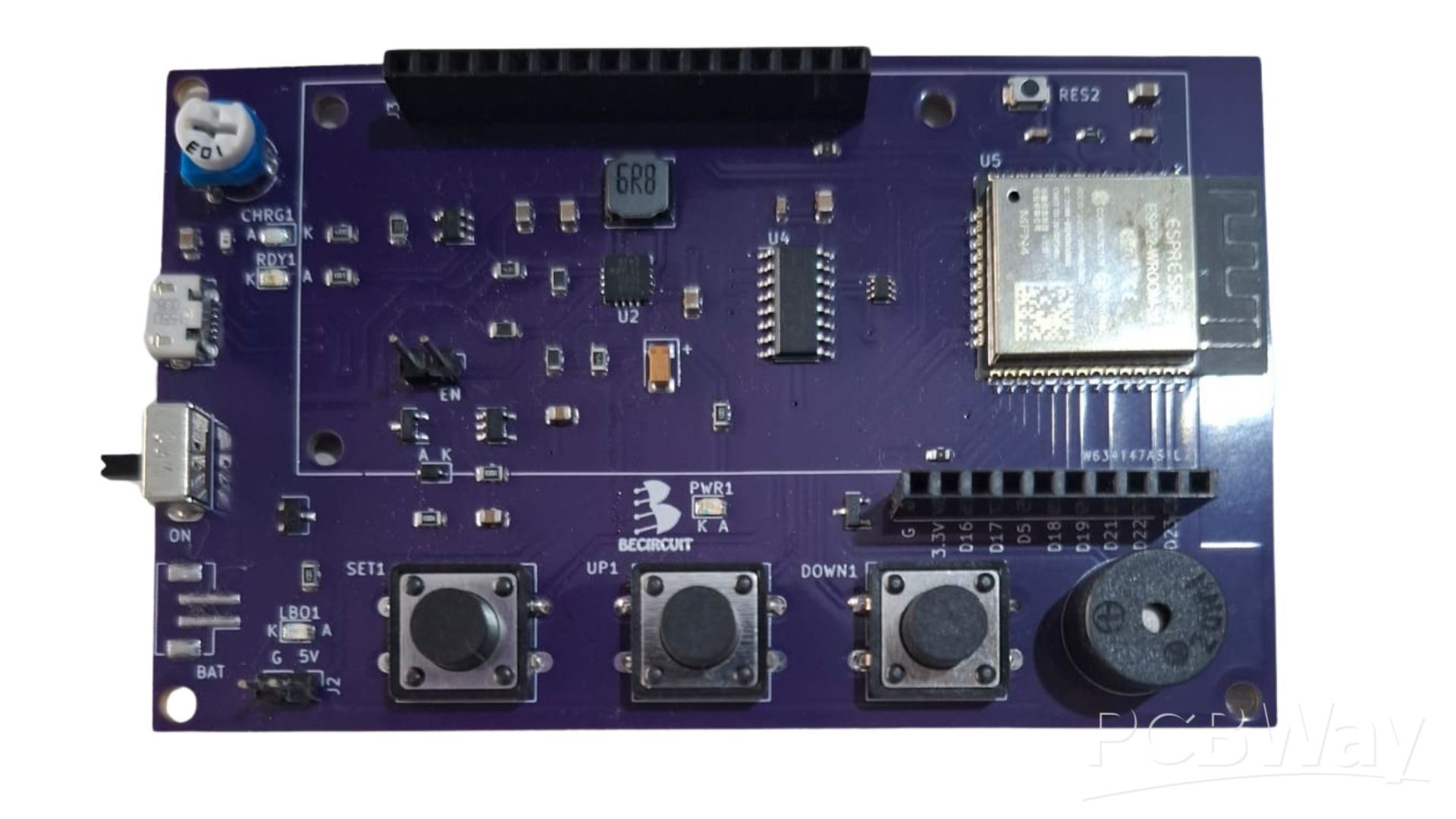
The ESP32 was chosen for its low power consumption and multiple I/O options. The LCD display is connected using the control pins RS, EN, RW, and data pins D4–D7. However, you can also use a 16x2 LCD with an I2C module using GPIO 21 (SDA) and GPIO 22 (SCL), which simplifies wiring and reduces complexity. The buttons are directly connected to GPIOs configured with internal pull-up resistors. The buzzer is controlled from a digital output using the tone() function.
Another reason I chose the ESP32 for this project is its built-in Bluetooth and WiFi capabilities, which open the door to many additional features such as remote monitoring and control. Although the main application is a Pomodoro timer, this board is programmable, allowing future upgrades such as a real-time clock function, using an internal timer or fetching the current time from an NTP server. Additional features like a countdown timer and stopwatch can also be added.
The PCB was designed as a two-layer board, paying attention to signal routing and separating power and control lines to minimize interference.
Power Supply Options:
This board can be powered in three different ways:
4.1. Via the USB port, supplying 5V to the LCD and then regulated to 3.3V for the ESP32.
4.2. Through a 2-pin header connector from an external 5V source, also regulated to 3.3V for the ESP32.
4.3. Using a 3.7V LiPo battery, which goes through a DC-DC converter to boost to 5V for the LCD and then regulated to 3.3V for the ESP32.
5. PCB Manufacturing
I exported the Gerber files from KiCad and uploaded them to PCBWay’s platform. Within a few days, I received the boards in Argentina with excellent build quality and clear silkscreen printing. PCBWay is a professional PCB manufacturing company offering reliable and fast service for students, makers, and professionals alike. I also took advantage of PCBWay’s assembly service, which is especially useful since the design includes surface-mount components that require specialized machines to assemble.
6. Arduino IDE Programming
To program the ESP32, I used the Arduino IDE. I installed the ESP32 board package via the board manager and added the required libraries for the LCD and button management. The main logic is based on states: time setup, countdown, pause, and sound alert at the end of the Pomodoro cycle.
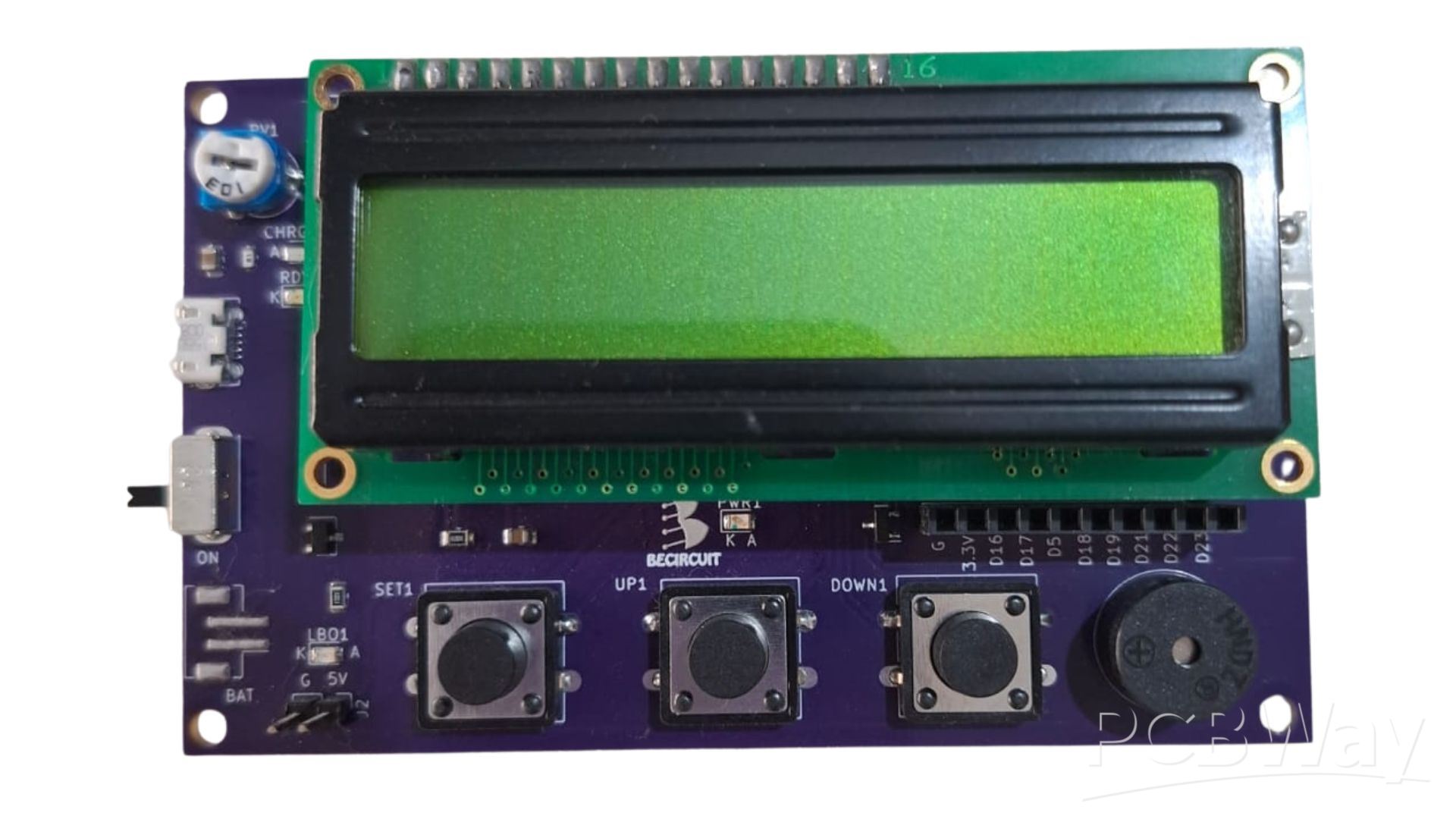
7. Assembly and Testing
Once I received the boards, I tested each part of the circuit incrementally — starting with the LCD, then the buttons, and finally the buzzer. The ESP32 was powered via USB during development to make programming and testing easier.
8. Results and Learnings
The final result is a compact, functional, and very practical timer for studying or working. The project helped me reinforce my knowledge of PCB design, peripheral interfacing, and event-driven programming. Having a dedicated device — separate from my phone — really makes a difference in staying focused.
As a future improvement, I would connect the LCD backlight pin (A or LED+) directly to 5V to keep the screen lit. If I wanted to control the backlight from a digital pin, I would use a transistor as a switch so that it receives 5V when activated. The current setup doesn't allow for this; directly connecting a digital pin to the A pin is not effective for turning on the backlight.
9. Conclusion
This project allowed me to bring together concepts of electronics, design, and programming into a real and useful device. It's an excellent project for anyone starting out with PCB design who wants to apply their skills in a fun and functional way.
YouTube video with full project explanation:


