In this short descriptive article, I will show you how to make a Line Follower Robot Car using Arduino UNO and 2 IR Sensor Modules. The name Line follower name suggests a Fully Automated Car. That follows a visual line (Most likely white or Black) that is embedded on any floor or any surface.
This project is based upon a microcontroller more specifically Arduino. But it is also possible to develop a line follower robot without a microcontroller. But there will be limited functionality and the stopped will be lower than any microcontroller-based vehicles.
Because the data processing power of the Microcontrollers is greater than simple Op-Amp ICs. This will be a basic line follower robot project report ppt.
Arduino Line Follower Robot with IR Sensor, Arduino Uno and L298N Motor Driver
How does the Line Follower Robot Car work?
This is a simple Microcontroller-based car. Let me tell you in detail how the thing works. The car consists of 2 IR sensors.
This sensor senses the line color is reflective or not. Here reflection means the surface sends back the light. In this case, the reflective surface is the White surface. (The non-reflective surface is the black lines only.) It means that that black tracks don’t reflect any light back.
The working of the sensor is that it senses is there any reflective light coming back or not. then only the sensor will give the output(Output two types. I will discuss that later). And if there is no reflection then the IR sensor will not give any output or in other words, the output will be low.
Based on this High and Low Output results the microcontroller can control the car.
The microcontroller gives the direction to the car where to go and then when to take turns (Left or Right) and where to stop (I created the code in such a way if the 2 sensors get Black Surface then it will tell the microcontroller to stop the car.).
Schematics for Arduino Line Follower Robot Car:
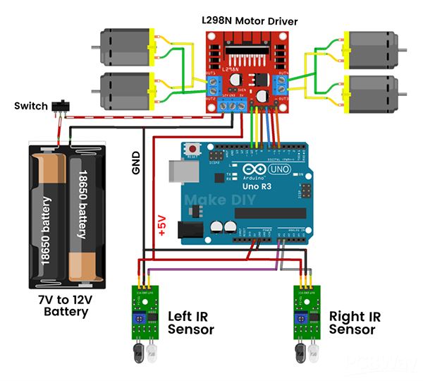
Arduino Line Follower Robot with IR Sensor, Arduino Uno and L298N Motor Driver
Steps for making the Car:
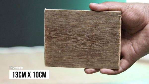
Step 1:
First, we will need a wood piece as the car chassis. Here I am using 13CM x 10CM Plywood as the car chassis. These dimensions are ideal for making a TT Motor Car. You can also use an Acrylic sheet or Premade chassis also.
Step 2:
Now attach the motors on the 4 corners of the Plywood with a Glue gun or any other glue. Make sure when you are attaching the motors then the motor alignment should be correct. Otherwise, the car will not go straight.

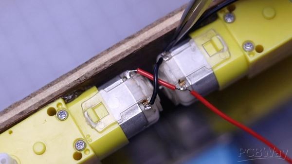
Step 3:
Now connect the TT Gear Motors as shown below. We will connect the motors in criss cross pattern. This is because we have to make the car in such a way that two side motor rotates in same direction in order to go Forward Backward and other known directions.
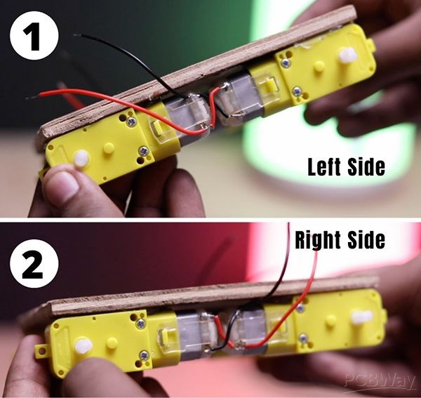
Step 4:
After Connecting motors, the connection should look like this. Here I provided both side pictures for you to understand clearly what is going on.
Step 5:
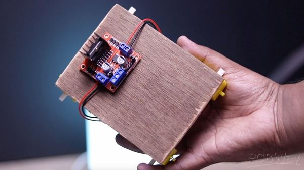
Here we are using L298N Motor Driver. I used double-sided tape for connecting the L298N Motor driver on the Plywood. You can also use Nut and bolts for this.

Step 6:
Now connect the motor wires with the L298N Motor Driver. And then Tighten the motor driver wires. and avoid any type of loose connection.
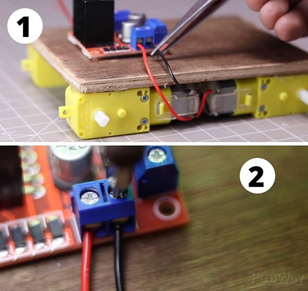
After connections all wires will look like this.
Note: After uploading the code if the car is not going in the right direction or if it is rotating in the wrong direction then just change the motor wires. And it will just work just fine.
Step 7:
For the Battery, I am using 2, 18650 batteries. This is great for making this type of car. For connecting the batteries I am using a 2s 18650 Battery holder. I also added a switch for turning on/ off the car.
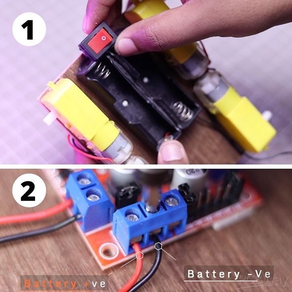
The battery wires will be connected with the motor driver input wires. You can also clearly see where to connect the battery wires.
Step 8:
In this project, I am using Arduino Uno as a Microcontroller. You can also use any other microcontroller as your wish. But in that case, the wiring schematics will be different.

Next, you have to remove the Jumper shorted connectors from the motor driver for the next step of connection.
Step 9:
In the picture I have mentioned the necessary connections for the motor driver.


Step 10:
Connect the IR Sensors as I showed in the photo. Then connect the necessary wires with the Arduino UNO. Just Follow the Wiring Diagram in the schematics.
Now Upload the code to Arduino. Now we have to do the calibration for running the car.

Step 11:
Connect the batteries to the car and turn on the switch.

Step 12: (Sensor Calibration) *** IMPORTANT***
Before calibrating you must connect the wheels to the car. You don’t need to open the serial monitor for calibration. It is just manual calibration. Here I used the digitalRead function to differentiate between Light and Dark. So, the IR Sensor will just give High/ Low as the Output.
Place the car on some High surface. Here I used a Top cover of Spray Paint to place the car on it for calibration. Here I am using the White surface couple with a T-shaped line for calibration. (Those who are thinking about what I used for the T Shape. Here is the answer, This is simple Black Electrical tape )

Place the car As I Showed in the picture. Now You are ready to calibrate. First Rotate the 2 Potentiometers (Left & Right side sensors both) full Counter-clockwise.
So, the calibration process is bit easier in this case. Now you can turn on the car and place on the where you want to follow and the car will follow the line.
Arduino Line Follower Car Code:
/*
Code Name: Arduino Line Follower Robot Car
Code URI: https://circuitbest.com/category/arduino-projects/
Author: Make DIY
Author URI: https://circuitbest.com/author/admin/
Description: This program is used to make Arduino Line Follower Robot Car.
Note: You can use any value between 0 to 255 for M1_Speed, M2_Speed, LeftRotationSpeed, RightRotationSpeed.
Here 0 means Low Speed and 255 is for High Speed.
Version: 1.0
License: Remixing or Changing this Thing is allowed. Commercial use is not allowed.
*/

#define in1 9
#define in2 8
#define in3 7
#define in4 6
#define enA 10
#define enB 5


 int M1_Speed = 80; // speed of motor 1
 int M2_Speed = 80; // speed of motor 2
 int LeftRotationSpeed = 250; // Left Rotation Speed
 int RightRotationSpeed = 250; // Right Rotation Speed


 void setup() {

 pinMode(in1,OUTPUT);
 pinMode(in2,OUTPUT);
 pinMode(in3,OUTPUT);
 pinMode(in4,OUTPUT);

  pinMode(enA,OUTPUT);
  pinMode(enB,OUTPUT);

   pinMode(A0, INPUT); // initialize Left sensor as an input
   pinMode(A1, INPUT); // initialize Right sensor as an input

}

void loop() {

 int LEFT_SENSOR = digitalRead(A0);
 int RIGHT_SENSOR = digitalRead(A1);

if(RIGHT_SENSOR==0 && LEFT_SENSOR==0) {
  forward(); //FORWARD
}

 else if(RIGHT_SENSOR==0 && LEFT_SENSOR==1) {
  right(); //Move Right
 }

 else if(RIGHT_SENSOR==1 && LEFT_SENSOR==0) {
  left(); //Move Left
}

 else if(RIGHT_SENSOR==1 && LEFT_SENSOR==1) {
  Stop(); //STOP
 }
}


void forward()
{
      digitalWrite(in1, HIGH);
      digitalWrite(in2, LOW);
      digitalWrite(in3, HIGH);
      digitalWrite(in4, LOW);

        analogWrite(enA, M1_Speed);
        analogWrite(enB, M2_Speed);
}

void backward()
{
      digitalWrite(in1, LOW);
      digitalWrite(in2, HIGH);
      digitalWrite(in3, LOW);
      digitalWrite(in4, HIGH);

        analogWrite(enA, M1_Speed);
        analogWrite(enB, M2_Speed);
}

void right()
{
      digitalWrite(in1, LOW);
      digitalWrite(in2, HIGH);
      digitalWrite(in3, HIGH);
      digitalWrite(in4, LOW);

        analogWrite(enA, LeftRotationSpeed);
        analogWrite(enB, RightRotationSpeed);
}

void left()
{
      digitalWrite(in1, HIGH);
      digitalWrite(in2, LOW);
      digitalWrite(in3, LOW);
      digitalWrite(in4, HIGH);

        analogWrite(enA, LeftRotationSpeed);
        analogWrite(enB, RightRotationSpeed);
}

void Stop()
{
      digitalWrite(in1, LOW);
      digitalWrite(in2, LOW);
      digitalWrite(in3, LOW);
      digitalWrite(in4, LOW);
}
Simple troubleshoot if the car is not going in the right direction:
If this happens and your car is not going in the right direction then you don’t have to modify any code. You have to just change the motor driver wires. Now your car will go in the right direction.

Line follower Car Demo
I have also created a simplified PCB for the Line follower Robot car that you can order from PCBWay.

I have designed the Schematics in EasyEDA.
All necessary connections are provided to the car like Power In, L298N Motor Driver Pinout, Left IR sensor, and Right IR sensor pinout..

PCB Layout
Here I used Atmega328P Microcontroller. This IC is also used in Arduino Uno R3. So, we will just program the Arduino UNO R3 and remove the chip from UNO Board and place it on the PCB. This will give the minimal look to the Car.

PCB 3D View
Conclusion:
All in all this is a great car for hobbyists. Make sure you do all the steps I have shown in the video. The speed of the car is low for following the line efficiently. If you want to speed up the car then you can use IR Array. But it is a topic for another video. Hope you guys enjoyed by making this car.
I have also provided How to speed up the car while going to straight lines and angular rotation in the code. Just change the speed parameter according to your car. Don’t make the speed parameter too much otherwise, the car will not able to make any quick rotation.
This is the only corn of the car. It is a great project for hobbyists. You can make this for fun projects as well as science projects.
Note: The content and the pictures in this article are contributed by the author. The opinions expressed by contributors are their own and not those of PCBWay. If there is any infringement of content or pictures, please contact our editor (zoey@pcbway.com) for deleting.
Written by