


Make Your OWN Solenoid Driver
Learn how to mill a solenoid driver PCB using your Bantam Tools Desktop PCB Milling Machine! This driver board has five 12V channels to drive multiple solenoids, relays, or valves directly from an Arduino board. Let’s get milling!
Step 1: Gather Your Tools and Materials
TOOLS
Bantam Tools Desktop PCB Milling Machine
Computer with Bantam Tools Desktop Milling Machine Software installed
Alignment bracket
Soldering iron
Diagonal wire clippers
MATERIALS
Tape, high-strength, double-sided
Solenoids, 12V 1a (5)
Transistors, TIP120 (5)
Screw terminals, 1x2, .1" pitch (9)
Resistors, 2.2K (5)
Diodes, 1N4001 (5)
Arduino Uno or similar
FILES
Download the Solenoid-Driver-PCB file.
Step 2: Set Up Your Job
Before you begin, install and locate the alignment bracket. Using the alignment bracket will ensure that your board is perfectly squared in the front left corner. After you install the alignment bracket, under Fixturing, select Locate, and follow the instructions on the screen.
Note: If you haven’t installed the alignment bracket before, follow the steps in this support guide.
With the alignment bracket installed, it’s time to set up your job. We’re going to run through this setup quickly. If you need more guidance on how to load your tool and enter information into the Bantam Tools Desktop Milling Machine Software, refer to the Light-Up PCB Badge project.
- Connect the Desktop PCB Milling Machine to your computer and open the Bantam Tools Desktop Milling Machine Software.
- Home the mill.
- Double-check to make sure it says Bracket under Fixturing.
- Select the 1/32" Flat End Mill, load it with the bit fan attached, and locate the tool.
- In the Material dropdown menu, select Single-Sided FR-1.
- Measure and enter dimensions in the X, Y, and Z values under Material. Then put high-strength, double-sided tape on one side of the PCB, and place it onto the spoilboard so it aligns with the right corner of the alignment bracket.
Step 3: Import Your File

In the Bantam Tools software, under Plans, click Open Files and select the Solenoid-Driver-PCB file. Then, select the 1/32" Flat End Mill. Your mill time will vary depending on the speeds and feeds recipe you use.
For this operation, we used the following recipe for the 1/32" flat end mill:
- Feed Rate: 60 in/min
- Plunge Rate: 15 in
- Spindle Speed: 22,000 RPM
- Stepover: 49%
- Pass Depth: 0.010 in
If you’d like to adjust your speeds and feeds to match ours, click File > Tool Library > Add Tool. Name your new tools and then input the speeds and feeds recipe. You can learn more about customizing your Tool Library here.
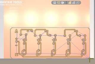
Then, click the button next to Parts to Mill so that “bottom” is selected.
The preview in the Bantam Tools software will look like the picture shown here.
TipQuestionComment
Step 4: Start Milling

When you’re done setting up your file, click Start Milling.
Step 5: Solder the Components


Time to solder! Grab your components and your soldering iron. It’s easiest to solder the components in the following order:
- Resistors
- Diodes
- Screw terminals
- TIP120s
- Heatsinks (optional)
As you’re assembling your solenoid driver, keep these addition design notes in mind:
- Each 12V solenoid has a 1N4001 diode in parallel with its positive/negative leads, serving as a flyback diode.
- The TIP120s serve as switches with signals being directed from the Arduino digital pins through a 2.2K resistor.
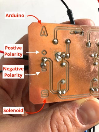
Additionally, note that the circuit board has Arduino signals coming in on one side, and the solenoids are being actuated on the other. This is indicated by an A (Arduino) and an S (solenoid) in each of the two rows.
External power (12V) enters through a screw terminal on the side of the board. Polarity is indicated with +/- symbols next to the screw terminals (where applicable). The solenoids are non-polar and can be oriented any way. Each Arduino screw terminal port is identical with the exception of one which is required for ground (as indicated by a “–” symbol). Arduino signal pins can be any digital pin.
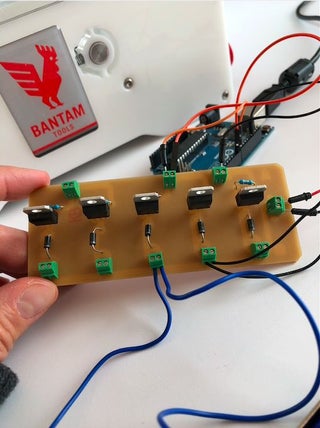
When you’re done soldering, the board will look like the last picture here. Note how the components go through the back side of the single-sided FR-1.
And there you have it: You’ve made a solenoid driver using your Desktop PCB Milling Machine!
Step 6: Test Your Solenoid Driver
With your solenoid driver assembled, now it’s time to test your PCB. Open up Arduino IDE and create a new sketch with the following code to test that each channel is working.
int solenoidPins[] = { 9, 10, 11, 12, 13 };
void setup()
{
setupPins(solenoidPins, 5); }
void loop() {
for (int i = 0; i < 5; i++) {
digitalWrite(solenoidPins[i], HIGH);
delay(80);
digitalWrite(solenoidPins[i], LOW);
delay(80);
}
}
//set the pins as outputs
void setupPins(int pins[], int lengthOfArray) {
for (int i = 0; i < lengthOfArray; i++) {
pinMode(pins[i], OUTPUT);
}
}
- Comments(0)
- Likes(0)
 More by Engineer
-
 Make Your own Smart Watch
This document is also translated in Polish(by Sebastian), Korean language.Various user made their ow...
Make Your own Smart Watch
This document is also translated in Polish(by Sebastian), Korean language.Various user made their ow...
-
 Vintage Flash Clock
Step 1: Parts & ToolsParts:1. Vintage Flash – check junk stores or if you have to, buy one from ...
Vintage Flash Clock
Step 1: Parts & ToolsParts:1. Vintage Flash – check junk stores or if you have to, buy one from ...
-
 Mini Weather Station Using Arduino Nano
This is a simple and fun project with pocket friendly budget....
Mini Weather Station Using Arduino Nano
Mini Weather Station Using Arduino NanoThis is a simple and fun project with pocket friendly budget....
-
 DIY IR Control Otto Bot
Thanks Pcbway For Your SupportCOMPONENTSIR transmitter (generic)×1ABOUT THIS PROJECTIntroductionIn t...
DIY IR Control Otto Bot
Thanks Pcbway For Your SupportCOMPONENTSIR transmitter (generic)×1ABOUT THIS PROJECTIntroductionIn t...
-
 Make Your OWN Solenoid Driver
Learn how to mill a solenoid driver PCB using your Bantam Tools Desktop PCB Milling Machine! This dr...
Make Your OWN Solenoid Driver
Learn how to mill a solenoid driver PCB using your Bantam Tools Desktop PCB Milling Machine! This dr...


