


DIY IR Control Otto Bot
Thanks Pcbway For Your Support
COMPONENTS
IR transmitter (generic)×1
ABOUT THIS PROJECT
Introduction
In this report we will explain the operation of a bipedal robot driven by
microcontrollers and controlled by a remote, able to walk and turn around.
Goal
The machines and projects must include the following features:
? use an Arduino microcontroller board (UNO, Leonardo, 101);
? request at least the use of an input sensor;
? generate at least one output interfacing with the real world, which can be visual (LED, screens) or physical (moving motors);
? use at least one device not explained in class, it can be a sensor or a motor and its pilot card.
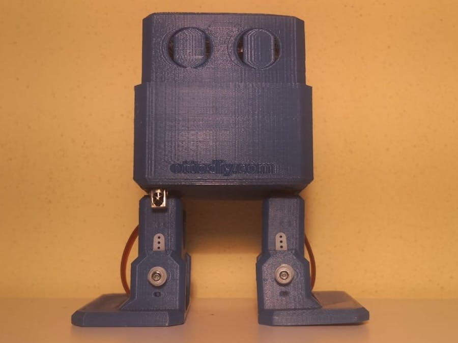
The project we decided to build is a toy bipedal robot (taking the "Otto DIY" open source project as an example) able to walk and turn around using an Arduino board which is controlled by IR signals sent by another Arduino board (which will work as a remote control).
Used Material
The components necessary for the realization of the project are the following ones:
- 2x Microcontroller (Arduino UNO, Elegoo Nano);
- 4x Micro servo SG90;
- IR LED;
- IR receiver VS1838B;
- joystick module;
- 100? resistance;
- Arduino nano expansion board;
- Jumper cables;
- PLA pieces (obtained by 3D printing).
The printed pieces’ 3D drawing files were downloaded from the website “Thingiverse”, as “Otto DIY” is an open source project.
The servos and the IR receiver don’t require any resistance as it’s integrated in the components.
To make the robot’s wirings easier we mounted the Elegoo Nano on an expansion board.
Functioning
To make the bipedal robot we used 2 microcontrollers.
The first one is an Elegoo Nano board connected to the joystick module and to the IR LED to assume the function of a remote control: it calculates the position of the joystick to understand where the robot has to go (so, which code has to be sent).
The second microcontroller is the “mind” of the robot: it controls the movements of the 4 servos based on the infrared signals received by the sensor. The operation of both devices are described in the following flowcharts.
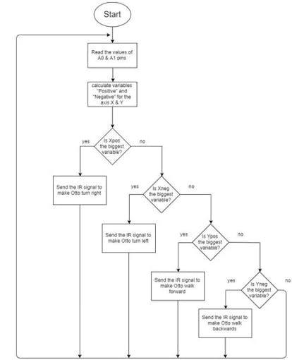
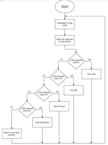
- 1
- 2
Conclusion
To complete this project we had to deal with many problems and to learn how to solve them (for example, the Elegoo nano board didn’t have integrated connectors so, to make it work properly, we had to solder all the pins).
Other than that, we learned also how to work with components and technologies never studied before which was the main goal of the exercise.
CODE
- Code Robot
- Code Remote
Code RobotC#
#include <IRremote.h>
#include <Otto9.h>


Otto9 Otto; //this is the name of our robot :)

IRrecv ir(12); //name and pin of the IR sensor
decode_results results; //this variable will assume the values of the recieved signals

#define PIN_LLEG 3 //YL - left leg pin
#define PIN_RLEG 4 //YR - right leg pin
#define PIN_LFOOT 2 //RL - left foot pin
#define PIN_RFOOT 5 //RR - right foot pin

#define PIN_Trigger  8 //US send pin
#define PIN_Echo     10 //US return pin
#define PIN_Buzzer  13 //buzzer pin

void setup() {

  //initialisation of the robot by defining: YL, YR, RL, RR, load calibration (true or false), Noise sensor, Buzzer, Trigger, Echo
  Otto.init(PIN_LLEG, PIN_RLEG, PIN_LFOOT, PIN_RFOOT, false, A6, PIN_Buzzer, PIN_Trigger, PIN_Echo);
  Otto.home(); //set all the servos to 90

  delay(500);
  Serial.begin(9600);
  ir.enableIRIn(); //start to read the IR sensor values
}

void loop() {

  if (ir.decode(&results)) {

    if (results.value == 24) { //if the code sent by the remote is 24:
      Otto.walk(8, 600, 1); //walk: 8=steps, 600=period (time per step), 1=direction (forward)
      Serial.println("forward");
    }

    if (results.value == 32) { //if the code sent by the remote is 32:
      Otto.walk(8, 600, -1); //walk: 8=steps, 600=period (time per step), -1=direction (backwards)
      Serial.println("backwards");
    }
    if (results.value == 8) { //if the code sent by the remote is 8:
      Otto.turn(8, 800, 1); //turn: 8=steps, 600=period (time per step), -1=direction (right)
      Serial.println("right");
    }
    if (results.value == 16) { //if the code sent by the remote is 16:
      Otto.turn(8, 800, -1); //turn: 8=steps, 600=period (time per step), -1=direction (left)
      Serial.println("left");
    }
    ir.resume(); //start reading the sensor values again
  }
  else { //if the robot doesn't recieve any signal
    Otto.home();
  }
  results.value = 0;
}
CUSTOM PARTS AND ENCLOSURES
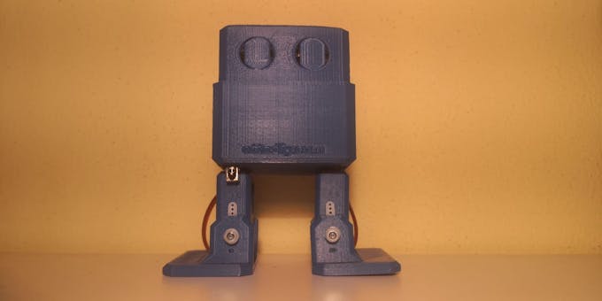
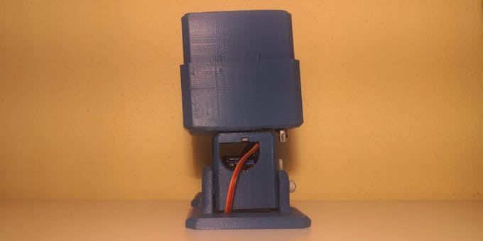
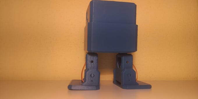
3D Printed parts
The parts we used to assembly the robot.
SCHEMATICS
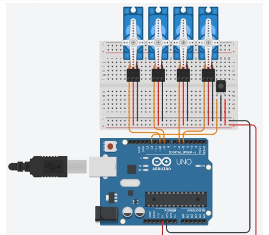
Circuit Robot
This is the robot circuit, made on Tinkercad
Circuit Remote
this is the Remote circuit, made on Tinkercad
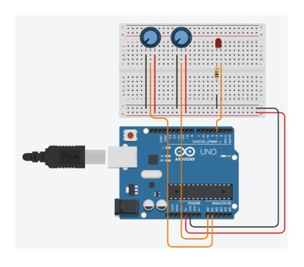 .
.
Thanks Pcbway ??
- Comments(0)
- Likes(0)
 More by Engineer
-
 Make Your own Smart Watch
This document is also translated in Polish(by Sebastian), Korean language.Various user made their ow...
Make Your own Smart Watch
This document is also translated in Polish(by Sebastian), Korean language.Various user made their ow...
-
 Vintage Flash Clock
Step 1: Parts & ToolsParts:1. Vintage Flash – check junk stores or if you have to, buy one from ...
Vintage Flash Clock
Step 1: Parts & ToolsParts:1. Vintage Flash – check junk stores or if you have to, buy one from ...
-
 Mini Weather Station Using Arduino Nano
This is a simple and fun project with pocket friendly budget....
Mini Weather Station Using Arduino Nano
Mini Weather Station Using Arduino NanoThis is a simple and fun project with pocket friendly budget....
-
 DIY IR Control Otto Bot
Thanks Pcbway For Your SupportCOMPONENTSIR transmitter (generic)×1ABOUT THIS PROJECTIntroductionIn t...
DIY IR Control Otto Bot
Thanks Pcbway For Your SupportCOMPONENTSIR transmitter (generic)×1ABOUT THIS PROJECTIntroductionIn t...
-
 Make Your OWN Solenoid Driver
Learn how to mill a solenoid driver PCB using your Bantam Tools Desktop PCB Milling Machine! This dr...
Make Your OWN Solenoid Driver
Learn how to mill a solenoid driver PCB using your Bantam Tools Desktop PCB Milling Machine! This dr...


