


How to Configure NeoPixels Using Vixen Lights and Arduino
What is Vixen Lights?
Vixen Lights is software for do-it-yourself lighting automation displays. The latest version 3.x was a complete redesign to support addressable “pixel” lights.
You can download it at http://www.vixenlights.com/downloads/ This tutorial is based on versión 3.4u2 64 Bit.
What is a Pixel?
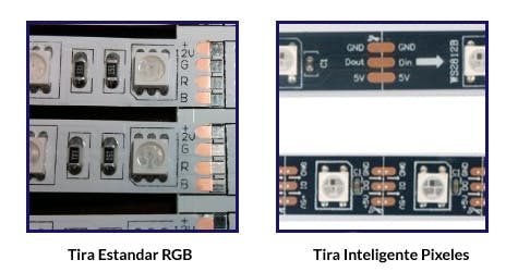
A pixel is a cluster of 3 Light Emitting Diodes (LEDs) consisting of the three primary colors (Red, Green and Blue). The intensity of these three colors (LEDs) can be varied to make other colors. The WS2812B pixels I am using in my example include an Integrate Circuit (IC) chip which accepts data in on one port, displays the information that was addressed to it and passes on data to the next pixel. For my display I purchased strings of 5 meters which have 30 pixels for every meter or 150 pixels for 5 meters. Addressable RGB “pixel” strips can usually be identified because they have 3 wires. One for power, one for ground and one for data. In contrast, RGB “dumb” strips can be identified by them having 4 wires. Usually one for power and one for each color Red, Green and Blue
RGB Pixels use a LOT of power. While the Arduino board can power up a few pixels using the built in voltage regulator, you will quickly run out of power. Therefore we will want to use an external power supply to power the lights. The voltage required will depend on the specific lights you have purchased. The lights I am using are 5V (volt). Another requirement of a power supply is to ensure it has enough power to support the number of pixels you are using. Each pixel at full white requires approximately 60 milliamps. for 150 RGB Pixels that works out to approximately 9A (Amps).
Unfortunately, the thin copper traces used on most LED strips causes “resistance” which will lead to dropping voltage levels. If the voltage at the pixel drops too low it can cause various problems such as flicker, dim lights or simply failure to light up. To avoid these issues, you may find that you will need to “insert” power at points within the RGB Pixel Strip. You would cut the strip and then just jump the DATA line across and add a new set of POWER and GROUND wires running back to your power supply. But be aware, that the distance of your power wire will also cause resistance and result in voltage drop. To avoid this, you must use wire that is thick enough based on your power requirements. The following chart is a decent starting point for choosing the right size of power
Bigger is always better when it comes to a power supply. You will need something that can provide more power (Amps) then you require. In my case I have ordered a couple of medium sized power supplies, 40 Amp and 60 Amp. Multiple power supplies can be used however, you should connect all of the ground wires for the power supplies together.
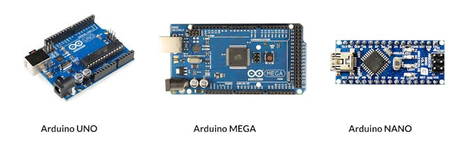
Arduino Controller
Many of the main stream Arduino boards can be used as a controller to become the middle man between the computer running Vixen Lights and the actual RGB Pixel Strips.
Various boards have different hardware limitation such as processor speed, memory (RAM) size and storage size. However in testing, the biggest limiting factor we found was the speed of the Serial Port. Most Arduinos can not go any faster than 115,200 bps. When we push the color codes for each of the three colors for 150 Pixels (aka 450 colors) down the serial port at 115,200 bps we can calculate that it will take 45 milliseconds to complete the transmission. This means we can safely refresh each pixel every 50 milliseconds (or 20 times per second).
The Code on this Tutorial is base in David Hunt - blog.huntgang.com
Configuring Vixen Serial Port
In order to use the Arduino controller, you must configure it inside of Vixen 3.x The following process was documented using
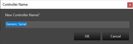
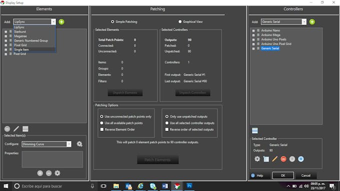
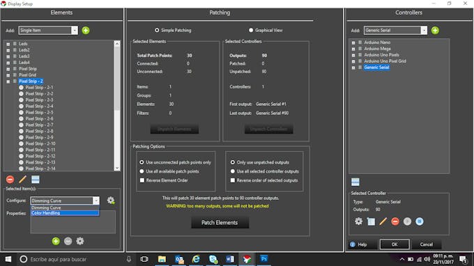
Step 1.- Add a Generic Serial Controller for the top right Menu.
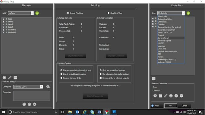
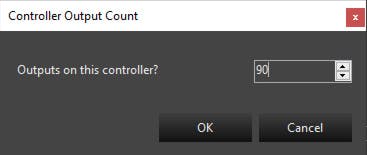
Step 2.- Set the number of outputs for the controller. This number should be 3x the number of pixels. In my example I am configuring 30 pixels which means I will set the output count to 90.
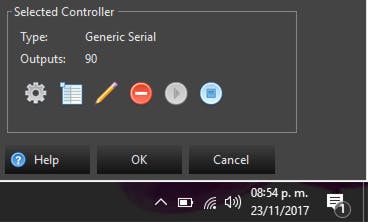
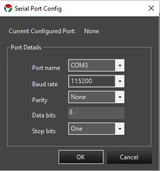
Step 3.- In the low right corner click the Gera Icon, now we will configure the COM Port. To do this we will select the COM port for the Arduino. My example is COM13 but yours will probably be different. We also want to configure the baud rate to 115200. The remainder of the settings can be left alone.

Step 4.- Here we will be adding the number of pixels into the header so that the Arduino knows how many pixels it should be receiving. The number of pixels must be 300 or less and must be entered as a three digit value. Again my example uses 030 pixels therefore I will be preceding it with two zeros. At this point you should see a bunch of blinky flashy on your Arduino as it is now receiving the serial data.
Configure Element for the Pixels
Step 5.- In the top left you will see a drop box, select Single Item, click on the Add Green button, and name it Pixel Strip.
Step 6.- Next we will right click on the Pixel Strip we just created and we will select Add Multiple. To add all of the pixels, we will select Numbered Items, define a name (I used Pixel Strip) and then select the number of pixels to generate (30 in my example). You should see all of the names in the list before clicking OK.


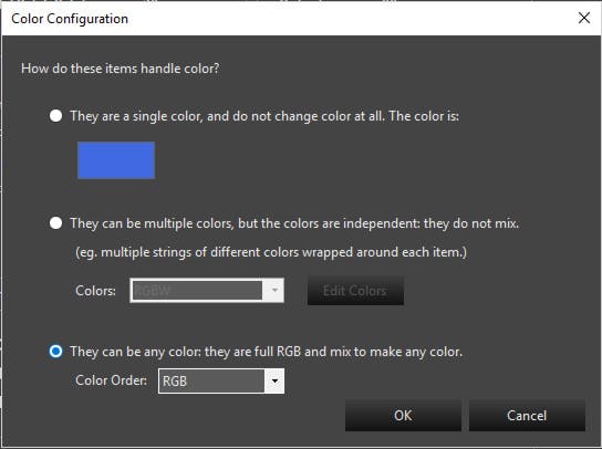
Step 7.- Now we will highlight the Pixel Strip and Configure the Color Handling property. We will select “They can be any color: they are full RGB and mix to make any color.”
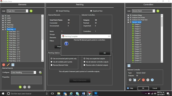
Step 8.- The final step before we can call it a day is to patch the Element to the Controller. To do this highlight the Pixel Strip on the left and the Generic Serial controller on the right. The number of Unconnected Patch Points should match. The only thing left to do is click Patch Elements to Controllers and then you are ready for Christmas Light.
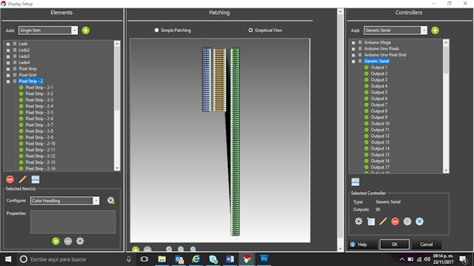
Step 9.- If you were successful your graphical view should look something like this.
Create my First Sequence
Step 10.- Open Vixen and click on New Sequence…

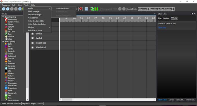
Step 11.- Import audio from the Tools menú, am using mp3.
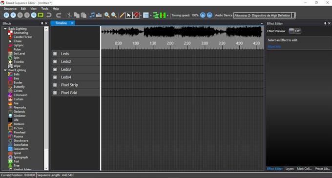
Step 12.-. If you were successful your screen look like ths, you can zoom in or zoom out using the zoom tool this will help in the Timeline.
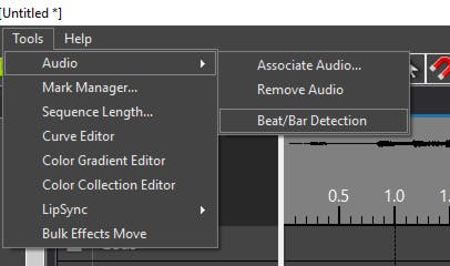
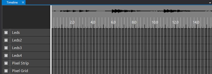
Step 13.- Now we go back to the Tools, Audio and select Beat/Bar Detector, this procces will help to aling perfectly the effects with the audio. You will see a lot of White lines.
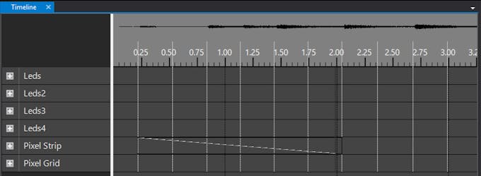
Step 14.- From the left Menu call Effects, ther are 2 submenus, Basic Lighting, Pixel Lighting, both menus can by use with pixels, let´s click on chase, Drag & drop un your Pixel Strip Line, use the mouse to resize the effect.
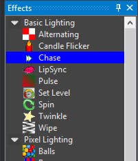
Note: In this example we are going to see, how the 30 pixels light up on a Chase mode.
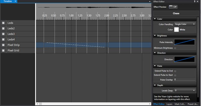
Step 15.- Select the Effect, in the ridh menú you will see more option to change direction, color, pulse, depth, etc., play with the effect, also you can actívate the Effect Preview.
Step 16.- Click Play on the Top Left corner, have fun, youtube has many samples.
Note: Ones your Arduino is connected to the computer and open the Vixen software you will see the RX on the Arduino flashing, this means that Arduino is wating for instructions from Vixen..
- Comments(0)
- Likes(0)
 More by Engineer
-
 Make Your own Smart Watch
This document is also translated in Polish(by Sebastian), Korean language.Various user made their ow...
Make Your own Smart Watch
This document is also translated in Polish(by Sebastian), Korean language.Various user made their ow...
-
 Vintage Flash Clock
Step 1: Parts & ToolsParts:1. Vintage Flash – check junk stores or if you have to, buy one from ...
Vintage Flash Clock
Step 1: Parts & ToolsParts:1. Vintage Flash – check junk stores or if you have to, buy one from ...
-
 Mini Weather Station Using Arduino Nano
This is a simple and fun project with pocket friendly budget....
Mini Weather Station Using Arduino Nano
Mini Weather Station Using Arduino NanoThis is a simple and fun project with pocket friendly budget....
-
 DIY IR Control Otto Bot
Thanks Pcbway For Your SupportCOMPONENTSIR transmitter (generic)×1ABOUT THIS PROJECTIntroductionIn t...
DIY IR Control Otto Bot
Thanks Pcbway For Your SupportCOMPONENTSIR transmitter (generic)×1ABOUT THIS PROJECTIntroductionIn t...
-
 Make Your OWN Solenoid Driver
Learn how to mill a solenoid driver PCB using your Bantam Tools Desktop PCB Milling Machine! This dr...
Make Your OWN Solenoid Driver
Learn how to mill a solenoid driver PCB using your Bantam Tools Desktop PCB Milling Machine! This dr...


