


|
KiCad 9.0 |
|

|
OnShapeOnShape
|
iCEPico - A RP Pico 2 Inspired FPGA Dev Board
iCEPico
========
A compact development board combining the RP2350 microcontroller and the ICE40UP5K-SG48I FPGA in a Raspberry Pi Pico form factor.
OVERVIEW
--------
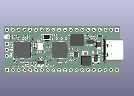
The iCEPico is a custom PCB that pairs the RP2350 with the Lattice ICE40UP5K-SG48I FPGA. The board is modeled after the Raspberry Pi Pico, with the addition of an FPGA and a 1.2V regulator to power it.
The board matches the physical dimensions of the Pico, though it does not replicate the Pico's pinout.
I created this project to learn FPGA design. Initially, I considered using a BGA package, but I chose a QFN package instead because of lower PCB costs and reduced design complexity. I had previously designed hardware using the RP2040 but had not worked with the RP2350. I plan to use this board as a general-purpose development platform, an FPGA learning tool, and a teaching aid for students in my school's robotics club.
A large portion of the project involved carefully implementing the RP2350 and iCE40UP5K FPGA on a compact four-layer PCB. I spent considerable time optimizing component placement, keeping decoupling capacitors close to their pins, and routing around the FPGA’s exposed pad, which made trace routing more challenging. I also paid close attention to clock signal integrity and power supply filtering to ensure reliable operation. The power system uses a 3.3V buck regulator and a 1.2V LDO for the FPGA core, with support for both USB-C and VIN power input. After several rounds of refinement and review, I am excited to move from design to fabrication and see the first physical version of the board assembled.
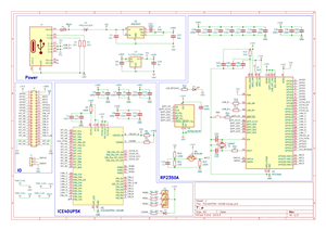
KiCanvas:
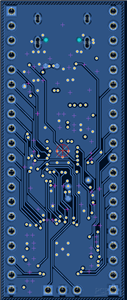
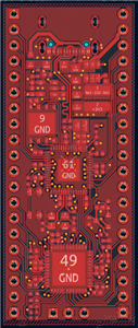
Board Images:
- Top View: Images/Top_View_PNG.png
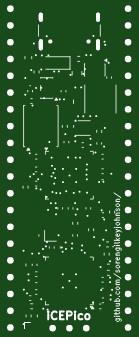
- Bottom View: Images/Bottom_View_PCB.png
- 3D Top: Images/ICE40UP5K-SG48I_3D_Top.png
- 3D Bottom: Images/ICE40UP5K-SG48I_3D_Bottom.png
Schematic PDF:
Images/ICE40UP5K-SG48I_Schematic.pdf
HARDWARE
--------
Microcontroller:
RP2350
FPGA:
Lattice ICE40UP5K-SG48I
QSPI Flash:
W25Q128JVP
3.3V Regulator:
AP63203 (Buck Converter)
1.2V Regulator:
TLV75612PDBV (LDO)
RP2350 <-> FPGA INTERCONNECT
----------------------------
The FPGA is configured by the RP2350 using a bit-banged programming interface. The two devices share 8 GPIO lines aligned with the RP2350's HSTX peripheral.
PCB STACK-UP
------------
Layer 1:
Signal routing and components
Layer 2:
Ground plane
Layer 3:
Power plane (primarily 3.3V)
Layer 4:
Signal routing
POWER
-----
The board can be powered through:
- USB-C:
5V VBUS through a Schottky diode
- VIN Header:
Direct voltage input
PROGRAMMING
-----------
USB (UF2) -> RP2350
Drag-and-drop bootloader over USB-C
SWD -> RP2350
Debug header for OpenOCD or probe-rs
Bit-bang via RP2350 -> ICE40 FPGA
FPGA bitstream loaded by RP2350 firmware
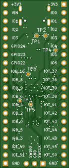
PINOUT
------
Pin Left Signal Right Signal Pin
-------------------------------------
1 GND +3V3 2
3 GPIO0 VIN 4
5 GPIO1 ADC2 6
7 GPIO2 ADC1 8
9 GPIO3 ADC0 10
11 GPIO4 GPIO24 12
13 GPIO5 GPIO23 14
15 GPIO6 GPIO22 16
17 IOT_37 IOB_16 18
19 IOT_36 IOB_8 20
21 IOT_39 IOB_9 22
23 IOT_38 IOB_6 24
25 IOT_41 IOB_4 26
27 IOT_42 IOB_2 28
29 IOT_43 IOB_0 30
31 IOT_44 IOB_5 32
33 IOT_48 IOB_3 34
35 GND GND 36
37 IOT_45 IOT_49 38
39 IOT_50 IOT_51 40
REPOSITORY STRUCTURE
https://github.com/SorenGilkeyJohnson/iCEPico
--------------------
iCEPico/
|
|-- Images/
| |-- Bottom_View_PCB.png
| |-- ICE40UP5K-SG48I_3D_Bottom.png
| |-- ICE40UP5K-SG48I_3D_Top.png
| |-- ICE40UP5K-SG48I_Schematic.pdf
| `-- Top_View_PNG.png
|
|-- KiCad/
| |-- ICE40UP5K-SG48I.kicad_pcb
| |-- ICE40UP5K-SG48I.kicad_prl
| |-- ICE40UP5K-SG48I.kicad_pro
| `-- ICE40UP5K-SG48I.kicad_sch
|
|-- fabrication/
| |-- bom.csv
| |-- gerbers.zip
| `-- pick_and_place.csv
|
|-- hardware/
| |-- ICE40UP5K-SG48I.kicad_pcb
| |-- ICE40UP5K-SG48I.kicad_pro
| `-- ICE40UP5K-SG48I.kicad_sch
|
|-- LICENSE
`-- README.md
LICENSE
CERN Open Hardware Licence Version 2
-------
iCEPico - A RP Pico 2 Inspired FPGA Dev Board
Project images are for reference only. Actual production is based on the manufacturing files on the project page.
Please review the designer's notes (e.g., PCB thickness) and select the appropriate options.
PCBWay is not responsible
for issues caused by unsuitable parameter selections.
For more important ordering information, please refer to
Read More


Raspberry Pi 5 7 Inch Touch Screen IPS 1024x600 HD LCD HDMI-compatible Display for RPI 4B 3B+ OPI 5 AIDA64 PC Secondary Screen(Without Speaker)
BUY NOW


- Comments(0)
- Likes(3)
 More by Engineer
-
Programmable Mist Maker - XIAO / QT PY Extension
1060 2 1 -
RadioHAT - Raspberry Pi radio development platform
858 0 2 -
-
-
-
-
ARPS-2 – Arduino-Compatible Robot Project Shield for Arduino UNO
3320 0 6 -
A Compact Charging Breakout Board For Waveshare ESP32-C3
3926 3 8 -
AI-driven LoRa & LLM-enabled Kiosk & Food Delivery System
4314 2 2


