


Talking Tom
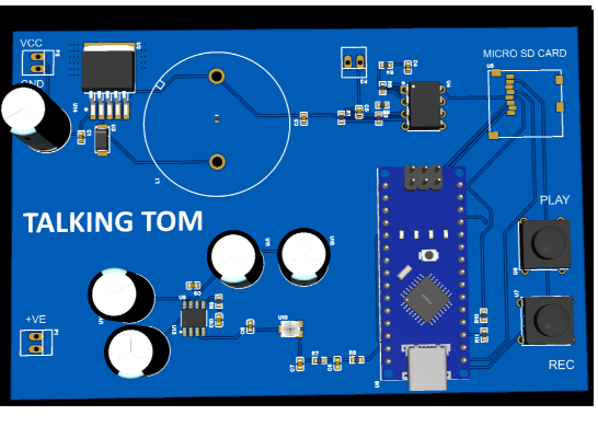
Talking Tom: Bare-Metal Voice Modulator & Raw SPI Flash Streamer
1. Project Overview
This project is a high-performance, real-time embedded digital signal processing (DSP) device named "Talking Tom". Built entirely on the 8-bit ATmega328P (Arduino Nano) platform, the system captures live human voice through an electret condenser microphone, saves the raw audio bytes directly into sector addresses on an SD card, and plays the recording back through a power amplifier with a hardware-driven chipmunk pitch acceleration.
To achieve maximum instruction efficiency and meet strict timing constraints, the firmware is written completely in bare-metal C without using any slow Arduino framework functions or generic external libraries.
2. Motivation
Standard hobbyist audio projects often rely heavily on generic audio shield libraries or high-level abstractions that introduce immense processing overhead and unpredictable timing lags.
This project was built to demonstrate that, with optimized circuit layouts and low-level bare-metal register manipulation, it is possible to implement high-speed real-time signal processing on a constrained 8-bit microcontroller.
It serves as an excellent demonstration of:
Low-noise analog signal conditioning
Hardware timer interrupt synchronization
Manual SPI peripheral master drivers
Custom PWM digital-to-analog reconstruction networks
3. System Operation
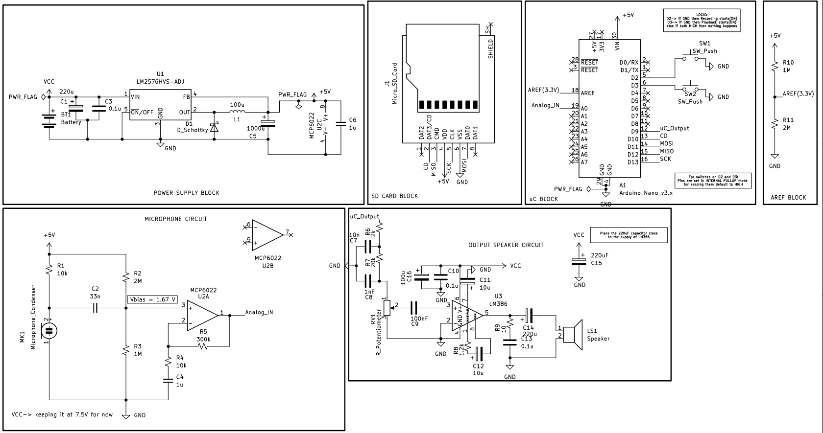
The device is divided into six functional hardware blocks that work together seamlessly.
A. Power Supply & Reference Blocks
LM2576HVS-ADJ Converter
Efficiently regulates raw battery power down to a stable +5 V rail to satisfy both noise-sensitive analog lines and digital components.
A massive 1000 µF capacitor filter protects the power rail from dropping when the MicroSD card draws current surges.
AREF Divider
A 1 MΩ / 2 MΩ resistor network establishes a clean 3.33 V external reference voltage directly on the AREF pin, shrinking full-scale steps to maximize effective ADC resolution.
B. Voice Capture Stage (Recording Mode)
MCP6022 Preamplifier
Takes millivolt signals from the electret capsule, applies an AC coupling capacitor to block phantom power, and routes the wave to a non-inverting amplifier stage with a gain of 31×.
The wave is centered perfectly around a stable 1.67 V DC offset to prevent clipping.
Timer1 Auto-Triggered ADC
Timer1 is configured in Mode 12 (CTC via ICR1) to cycle precisely at 16 kHz.
Each timer overflow flag directly auto-triggers an 8-bit ADC snapshot on pin A0.
Ping-Pong Buffer Storage
To prevent data loss while writing to storage, the code implements dual 512-byte RAM blocks.
While Timer1 fills Buffer 0, a background handler streams the previously completed Buffer 1 over an inline-optimized 8 MHz hardware SPI bus straight into raw sector addresses.
C. Audio Extraction Stage (Playback Mode)
Chipmunk Pitch Shift
The computer reads the saved audio blocks back from the MicroSD card.
Instead of pacing the output at the original 16 kHz speed, Timer2 triggers compare matches at a fast 29.41 kHz pace.
Dumping the data 1.84× faster than it was recorded squeezes the waves closer together, shifting the output frequencies upward into a funny chipmunk voice.
PWM Reconstruction
The output samples update the duty cycle of a Fast PWM carrier on pin D9 clocking at 62.5 kHz.
D. Speaker Amplification Stage
Demodulator & Filter
An RC low-pass filter (22 kΩ and 1 nF) smooths out the rough edges of the 62.5 kHz digital pulses, recovering a clean, smooth analog sound wave.
DC-Blocking Capacitor
A series 100 nF capacitor blocks the residual 2.5 V DC offset left behind by the PWM process, letting only safe AC audio pass into the power amplifier.
LM386 Stage
Amplifies the recovered wave to safely drive a robust 8 Ω, 10 W speaker load.
It includes:
A 10 µF bypass capacitor on Pin 7
An output Zobel network to suppress high-frequency noise
These additions help keep the amplifier running safely, cool, and loud.
// ============================================================
//  TALKING TOM — FINAL BARE-METAL FIRMWARE (PRODUCTION V3)
//  Target : Arduino Nano (ATmega328P @ 16 MHz)
//  Reference: External AREF (3.33V), Timer1 CTC Recording (16kHz),
//             Timer2 CTC Playback (29.4kHz), Fast PWM Output (D9)
// ============================================================

#define F_CPU 16000000UL

#include <avr/io.h>
#include <avr/interrupt.h>
#include <util/delay.h>
#include <stdint.h>
#include <stdbool.h>

// ============================================================
// SD CARD COMMANDS
// ============================================================
#define CMD0    0    // GO_IDLE_STATE
#define CMD8    8    // SEND_IF_COND
#define CMD17   17   // READ_SINGLE_BLOCK
#define CMD24   24   // WRITE_BLOCK
#define CMD55   55   // APP_CMD (prefix for ACMD)
#define ACMD41 41   // SD_SEND_OP_COND

// ============================================================
// BUFFER CONFIGURATION
// ============================================================
#define BUFFER_SIZE  512
#define START_BLOCK  100000UL   // Sector address safely past FAT structures

volatile uint8_t buffer0[BUFFER_SIZE];
volatile uint8_t buffer1[BUFFER_SIZE];

volatile uint16_t bufIdx       = 0;
volatile bool     usingBuffer0 = true;
volatile bool     writeFlag    = false;
volatile bool     readFlag     = false;

// ============================================================
// SYSTEM STATE
// ============================================================
typedef enum { IDLE, RECORDING, PLAYING } SystemState;
volatile SystemState currentState = IDLE;

// ============================================================
// SD CARD SECTOR VARIABLES
// ============================================================
uint32_t current_sd_block = START_BLOCK;
uint32_t max_sd_block     = START_BLOCK;

// BUG FIX: Added volatile to prevent compiler caching during high-speed loops
volatile bool isSDHC      = true;   // Forced true for modern 8GB SDHC block-addressing

// ============================================================
// FUNCTION DECLARATIONS
// ============================================================
void    spi_slow(void);
void    spi_fast(void);
uint8_t spi_transfer(uint8_t data);

uint8_t sd_send_command(uint8_t cmd, uint32_t arg, uint8_t crc);
bool    sd_init(void);
bool    sd_write_raw_block(uint32_t block, volatile uint8_t *buf);
bool    sd_read_raw_block (uint32_t block, volatile uint8_t *buf);

void startRecording(void);
void stopRecording(void);
void startPlayback(void);
void stopPlayback(void);

// ============================================================
// MAIN EXECUTION LOOP
// ============================================================
int main(void)
{
    // --- Button inputs with internal pull-ups (PD2 = REC, PD3 = PLAY) ---
    DDRD  &= ~((1 << PD2) | (1 << PD3));
    PORTD |=  (1 << PD2)  | (1 << PD3);

    // --- SPI pins: PB2=CS, PB3=MOSI, PB5=SCK outputs; PB4=MISO input ---
    DDRB |=  (1 << PB2) | (1 << PB3) | (1 << PB5);
    DDRB &= ~(1 << PB4);
    PORTB |= (1 << PB2);   // CS idle HIGH

    // --- PWM output on OC1A = PB1 (D9) ---
    DDRB |= (1 << PB1);

    // Track state variables for edge-detection (debouncing without blocking loops)
    uint8_t lastRecState  = 1;
    uint8_t lastPlayState = 1;

    spi_slow();

    if (!sd_init())
    {
        // SD init failed — halt system (Blink D13 LED as fallback indicator)
        DDRB |= (1 << PB5);
        while (1)
        {
            PORTB ^= (1 << PB5);
            _delay_ms(100);
        }
    }

    spi_fast();   // Switch to 8MHz full speed operational bus clock

    sei();

    while (1)
    {
        // --------------------------------------------------------
        // NON-BLOCKING EDGE-TRIGGER BUTTON POLLING
        // --------------------------------------------------------
        uint8_t currentRecState  = (PIND & (1 << PD2)) ? 1 : 0;
        uint8_t currentPlayState = (PIND & (1 << PD3)) ? 1 : 0;

        // Check REC Button: Falling Edge (Pressed)
        if (currentRecState == 0 && lastRecState == 1)
        {
            _delay_ms(20); // Quick contact bounce filter
            if ((PIND & (1 << PD2)) == 0)
            {
                if (currentState == IDLE)            startRecording();
                else if (currentState == RECORDING)  stopRecording();
            }
        }
        lastRecState = currentRecState;

        // Check PLAY Button: Falling Edge (Pressed)
        if (currentPlayState == 0 && lastPlayState == 1)
        {
            _delay_ms(20); // Quick contact bounce filter
            if ((PIND & (1 << PD3)) == 0)
            {
                if (currentState == IDLE)         startPlayback();
                else if (currentState == PLAYING) stopPlayback();
            }
        }
        lastPlayState = currentPlayState;

        // --------------------------------------------------------
        // BACKGROUND FLASH DATA STREAMING
        // --------------------------------------------------------
        if (currentState == RECORDING)
        {
            if (writeFlag)
            {
                // CRITICAL INTERRUPT LOCK: Disable ADC conversion interrupts to lock buffer
                // state while processing heavy raw SPI write operations.
                ADCSRA &= ~(1 << ADIE);

                // Stream out the inactive buffer that was just filled by the ISR
                if (!usingBuffer0)
                    sd_write_raw_block(current_sd_block, buffer0);
                else
                    sd_write_raw_block(current_sd_block, buffer1);

                current_sd_block++;
                max_sd_block = current_sd_block;
                writeFlag    = false;

                // Re-enable capture interrupts safely
                ADCSRA |= (1 << ADIE);
            }
        }
        else if (currentState == PLAYING)
        {
            if (readFlag)
            {
                if (current_sd_block >= max_sd_block)
                {
                    stopPlayback();
                }
                else
                {
                    // CRITICAL INTERRUPT LOCK: Temporarily mask out Timer2 sample ticks
                    // so the playback interrupt doesn't step on raw SPI clock transitions.
                    TIMSK2 &= ~(1 << OCIE2A);

                    // Fetch next data block into the empty buffer slot
                    if (!usingBuffer0)
                        sd_read_raw_block(current_sd_block, buffer0);
                    else
                        sd_read_raw_block(current_sd_block, buffer1);

                    current_sd_block++;
                    readFlag = false;

                    // Unpause audio pacing ticks safely
                    TIMSK2 |= (1 << OCIE2A);
                }
            }
        }
    }
}

// ============================================================
// LOW-LEVEL REGISTERS & COMMUNICATIONS
// ============================================================
void spi_slow(void)
{
    // Clock rate: fosc/128 = 125 kHz (compliant during card identification)
    SPCR = (1 << SPE) | (1 << MSTR) | (1 << SPR1) | (1 << SPR0);
    SPSR &= ~(1 << SPI2X);
}

void spi_fast(void)
{
    // Clock rate: fosc/2 = 8 MHz (maximum throughput execution speed)
    SPCR = (1 << SPE) | (1 << MSTR);
    SPSR = (1 << SPI2X);
}

uint8_t spi_transfer(uint8_t data)
{
    SPDR = data;
    while (!(SPSR & (1 << SPIF)));
    return SPDR;
}

uint8_t sd_send_command(uint8_t cmd, uint32_t arg, uint8_t crc)
{
    uint8_t response;
    spi_transfer(0xFF);
    PORTB &= ~(1 << PB2); // Assert CS LOW

    spi_transfer(cmd | 0x40);
    spi_transfer((uint8_t)(arg >> 24));
    spi_transfer((uint8_t)(arg >> 16));
    spi_transfer((uint8_t)(arg >>  8));
    spi_transfer((uint8_t)(arg));
    spi_transfer(crc);

    for (uint8_t i = 0; i < 10; i++)
    {
        response = spi_transfer(0xFF);
        if (response != 0xFF) break;
    }
    return response;
}

bool sd_init(void)
{
    uint8_t  response;
    uint16_t timeout = 0;
    _delay_ms(10);

    PORTB |= (1 << PB2); // CS HIGH
    for (uint8_t i = 0; i < 10; i++) spi_transfer(0xFF); // 80+ initialization clocks

    response = sd_send_command(CMD0, 0, 0x95);
    PORTB |= (1 << PB2); spi_transfer(0xFF);
    if (response != 0x01) return false;

    response = sd_send_command(CMD8, 0x000001AA, 0x87);
    if (response == 0x01)
    {
        spi_transfer(0xFF); spi_transfer(0xFF); spi_transfer(0xFF); spi_transfer(0xFF);
    }
    PORTB |= (1 << PB2); spi_transfer(0xFF);

    do
    {
        sd_send_command(CMD55, 0, 0xFF);
        PORTB |= (1 << PB2); spi_transfer(0xFF);

        response = sd_send_command(ACMD41, 0x40000000, 0xFF);
        PORTB |= (1 << PB2); spi_transfer(0xFF);

        timeout++;
        _delay_ms(1);
    }
    while (response != 0x00 && timeout < 1000);

    return (response == 0x00);
}

// ============================================================
// DIGITAL SIGNAL PROCESSING CONTROLLERS
// ============================================================
void startRecording(void)
{
    current_sd_block = START_BLOCK;
    bufIdx           = 0;
    usingBuffer0     = true;
    writeFlag        = false;

    cli();

    // Timer1 setup: Clear Timer on Compare Match (CTC) mode
    TCCR1A = 0x00;
    TCCR1B = (1 << WGM12) | (1 << CS11);   // Prescaler /8
    OCR1A  = 124;                           // 16,000,000 / (8 * 16,000Hz) - 1 = 124

    // ADC Setup: Clear Reference Bits to explicitly select External AREF Pin (3.33V)
    ADMUX = (1 << ADLAR);  // Left-adjusted results (read ADCH only for 8-bit resolution)
    DIDR0 |= (1 << ADC0D); // Disable digital input channel buffer on A0 pin

    // Auto-trigger target set to Timer1 Compare Match A (0 1 1 pattern)
    ADCSRB = (1 << ADTS1) | (1 << ADTS0);

    ADCSRA = (1 << ADEN)  | // Enable ADC
             (1 << ADATE) | // Enable Auto-Triggering
             (1 << ADIE)  | // Enable Conversion Complete Interrupt
             (1 << ADPS2) | (1 << ADPS1);  // Prescaler /64 (250kHz ADC clock)

    // BUG FIX: Manual ADSC strobe removed. Let Timer1 trigger the first capture cleanly.

    sei();
    currentState = RECORDING;
}

void stopRecording(void)
{
    ADCSRA &= ~(1 << ADEN); // Shut down ADC
    TCCR1A = 0x00;
    TCCR1B = 0x00; // Stop Timer1 sample clock

    // Complete, pad, and flush the open data block buffer to flash memory
    if (bufIdx > 0)
    {
        if (usingBuffer0)
        {
            for (uint16_t i = bufIdx; i < BUFFER_SIZE; i++) buffer0[i] = 127;
            sd_write_raw_block(current_sd_block, buffer0);
        }
        else
        {
            for (uint16_t i = bufIdx; i < BUFFER_SIZE; i++) buffer1[i] = 127;
            sd_write_raw_block(current_sd_block, buffer1);
        }
        current_sd_block++;
        max_sd_block = current_sd_block;
    }

    currentState = IDLE;
}

void startPlayback(void)
{
    current_sd_block = START_BLOCK;

    // Synchronously pre-fill audio cache slots before starting hardware timer interrupts
    sd_read_raw_block(current_sd_block++, buffer0);
    sd_read_raw_block(current_sd_block++, buffer1);

    bufIdx       = 0;
    usingBuffer0 = true;
    readFlag     = false;

    cli();

    // Timer1 Setup: Fast 8-bit PWM Generation mode on pin D9 (OC1A)
    TCCR1A = (1 << COM1A1) | (1 << WGM10);
    TCCR1B = (1 << WGM12)  | (1 << CS10);   // No Prescaler -> Carrier frequency = 62.5 kHz
    OCR1A  = 127;                           // Clear 50% midpoint duty cycle start

    // Timer2 Setup: CTC Mode running at 29.41 kHz sample transfer interrupts
    TCCR2A = (1 << WGM21);
    TCCR2B = (1 << CS21);      // Prescaler /8
    OCR2A  = 67;               // 16,000,000 / (8 * 29,412Hz) - 1 = 67 (~1.84x frequency shift)
    TIMSK2 = (1 << OCIE2A);    // Enable Timer2 Output Compare Match A interrupt

    sei();
    currentState = PLAYING;
}

void stopPlayback(void)
{
    TIMSK2 = 0x00; // Disable Timer2 pacing clock
    TCCR1A = 0x00;
    TCCR1B = 0x00;
    TCCR2A = 0x00;
    TCCR2B = 0x00; // Terminate Timer1 output PWM wave
    OCR1A  = 0;
    currentState = IDLE;
}

// ============================================================
// SYSTEM INTERRUPT HANDLERS
// ============================================================
ISR(ADC_vect)
{
    if (usingBuffer0) buffer0[bufIdx] = ADCH;
    else              buffer1[bufIdx] = ADCH;

    bufIdx++;
    if (bufIdx >= BUFFER_SIZE)
    {
        bufIdx       = 0;
        usingBuffer0 = !usingBuffer0;
        writeFlag    = true; // Flag main program loop to flash block to storage
    }
}

// ============================================================
// LM386 OUTPUT RECONSTRUCTION PUMP
// ============================================================
ISR(TIMER2_COMPA_vect)
{
    if (usingBuffer0) OCR1A = buffer0[bufIdx];
    else              OCR1A = buffer1[bufIdx];

    bufIdx++;
    if (bufIdx >= BUFFER_SIZE)
    {
        bufIdx       = 0;
        usingBuffer0 = !usingBuffer0;
        readFlag     = true; // Flag main program loop to update empty cache block
    }
}

// ============================================================
// LOW-LEVEL FLASH READ/WRITE OPERATIONS
// ============================================================
bool sd_write_raw_block(uint32_t block, volatile uint8_t *buf)
{
    uint32_t addr    = isSDHC ? block : block * 512UL;
    uint16_t timeout = 0;

    if (sd_send_command(CMD24, addr, 0xFF) != 0x00)
    {
        PORTB |= (1 << PB2);
        return false;
    }

    spi_transfer(0xFF);
    spi_transfer(0xFE); // Data Token

    for (uint16_t i = 0; i < BUFFER_SIZE; i++)
        spi_transfer(buf[i]);

    spi_transfer(0xFF);
    spi_transfer(0xFF); // CRC Block

    uint8_t resp = spi_transfer(0xFF);
    if ((resp & 0x1F) != 0x05)
    {
        PORTB |= (1 << PB2);
        return false;
    }

    while (spi_transfer(0xFF) == 0x00) // Wait out card programming status
    {
        timeout++;
        if (timeout > 65000U)
        {
            PORTB |= (1 << PB2);
            return false;
        }
    }

    PORTB |= (1 << PB2); // Raise CS HIGH
    spi_transfer(0xFF);
    return true;
}

bool sd_read_raw_block(uint32_t block, volatile uint8_t *buf)
{
    uint32_t addr    = isSDHC ? block : block * 512UL;
    uint16_t timeout = 0;

    if (sd_send_command(CMD17, addr, 0xFF) != 0x00)
    {
        PORTB |= (1 << PB2);
        return false;
    }

    while (spi_transfer(0xFF) != 0xFE) // Scan for data token
    {
        timeout++;
        if (timeout > 65000U)
        {
            PORTB |= (1 << PB2);
            return false;
        }
    }

    for (uint16_t i = 0; i < BUFFER_SIZE; i++)
        buf[i] = spi_transfer(0xFF);

    spi_transfer(0xFF);
    spi_transfer(0xFF);

    PORTB |= (1 << PB2); // Raise CS HIGH
    spi_transfer(0xFF);
    return true;
}
Talking Tom
*PCBWay community is a sharing platform. We are not responsible for any design issues and parameter issues (board thickness, surface finish, etc.) you choose.


Raspberry Pi 5 7 Inch Touch Screen IPS 1024x600 HD LCD HDMI-compatible Display for RPI 4B 3B+ OPI 5 AIDA64 PC Secondary Screen(Without Speaker)
BUY NOW


- Comments(0)
- Likes(1)
 More by Engineer
-
Programmable Mist Maker - XIAO / QT PY Extension
834 1 0 -
RadioHAT - Raspberry Pi radio development platform
671 0 2 -
-
-
-
-
ARPS-2 – Arduino-Compatible Robot Project Shield for Arduino UNO
3131 0 6 -
A Compact Charging Breakout Board For Waveshare ESP32-C3
3761 3 8 -
AI-driven LoRa & LLM-enabled Kiosk & Food Delivery System
4088 2 2


