
|
KiCADKicad
|
RPi Pico Project Board
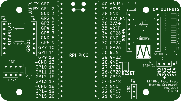
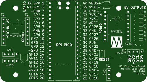
The purpose of this board is to make it quick and easy to get Raspberry Pi Pico projects up and running. It's a step up from just plugging the Pico into a breadboard. The key features are:
- Labelling: All the pins are labelled with their physical pin numbers and key function - eg, GND, GP7 etc.
- Reset button: A surface-mount tactile button pulls the RUN signal low to perform a board reset.
- 8 buffered 5V inputs: A buffer chip provides level shifting down from +5V to +3V3. Header pins allow you to connect any of these inputs to any of the Pico's GPIOs at a safe voltage.
- 8 buffered 5V outputs: Another buffer chip shifts signals up from +3V3 to +5V, allowing the Pico to work with 5V devices such as sensors, actuators etc. Again, header pins allow you to connect any of these inputs to any of the Pico's GPIOs.
- 8 LEDs: The outputs of the buffer chip have LEDs showing the signal state of connected devices, or you can just use the LEDs for debugging or output purposes.
- I2C port: The I2C0 port is broken out to four header pins (SDA, SCL, +3V3 and GND). The order of the pins is compatible with many small OLED modules. The SDA and SCL lines have 4.7kΩ pullup resistors.
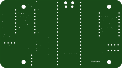
- Dual Pico footprint: The footprint for the Pico accommodates mounting it either directly soldered as a surface-mount device or via headers, so you can have the Pico permanently attached or removeable. The footprint also has a keepout area ensuring there are no copper layers or traces under the antenna area.
The board is designed to be powered via the USB on the Pico, although you could connected +5V directly to the Pico's VSYS pin.
This is a 4-layer board with dedicated GND and +3V3 planes on the inner layers.
Four mounting holes are provided, suitable for M3 hardware.
The BOM includes all surface-mount components, to which you’ll need to add 2.54mm-pitch header pins and the Pico board of your choice.
RPi Pico Project Board
Project images are for reference only. Actual production is based on the manufacturing files on the project page.
Please review the designer's notes (e.g., PCB thickness) and select the appropriate options.
PCBWay is not responsible
for issues caused by unsuitable parameter selections.
For more important ordering information, please refer to
Read More


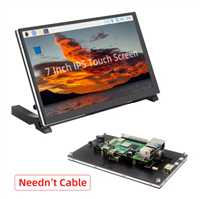
Raspberry Pi 5 7 Inch Touch Screen IPS 1024x600 HD LCD HDMI-compatible Display for RPI 4B 3B+ OPI 5 AIDA64 PC Secondary Screen(Without Speaker)
BUY NOW


- Comments(0)
- Likes(0)
More by Steve Mansfield-Devine
-
 ATtiny1604 Breakout Board
The ATtiny1604 is one of the 'new generation' of microcontrollers from Microchip (née Atmel). It pac...
-
 RPi Pico Project Board
The purpose of this board is to make it quick and easy to get Raspberry Pi Pico projects up and runn...
-
 SmartMatrix: networked parallel printer interface
The Raspberry Pi Pico 2W-based SmartMatrix adapter uses the microcontroller to convert serial or net...
-
 ATmega4809-A Breakout Board
A breakout board that allows you to easily work with the AVR 0-series ATmega4809-A microcontroller. ...
-
 Infrared IoT hub for home automation - ESP32 version
I created this as a way of experimenting with using IR signals to communicate with Internet of Thing...
-
-
-
-
AudioLink – USB & Bluetooth LE Audio / Auracast Receiver with Balanced Line Outputs (nRF5340)
337 0 1 -
-
-
-
Émetteur Récepteur Optique Expérimental (communication UART ATtiny + fibre optique)
392 0 1 -
SmallOLED - Live PC Stats, Animated Clocks & Audio Visualizer
1504 0 3