


MicroFC-SiPM-Array-Board
This is the affiliate page for the MicroFC SiPM Carrier Board.
NOTE: THIS IS A 4 LAYER BOARD!
You can easily order the PCB directly through PCBWay here — it helps support the project a little, and doesn’t cost you anything extra.
The main open-source project with all hardware, firmware, and documentation is hosted on GitHub.
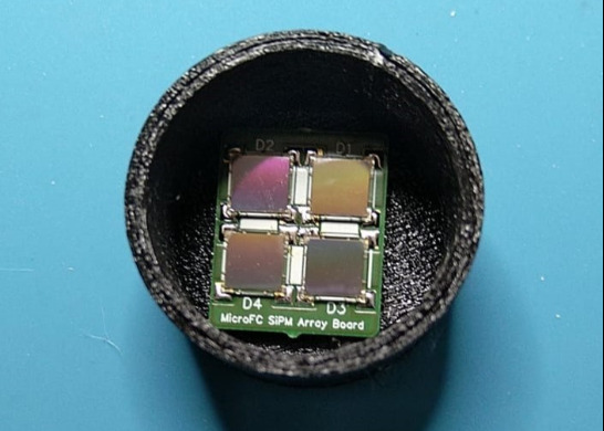
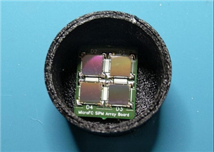
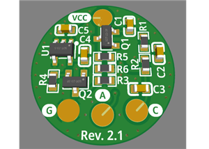
Carrier board for a 2 x 2 array of the 6 mm C-Series MICROFC-60035-SMT silicon photomultipliers by onsemi.
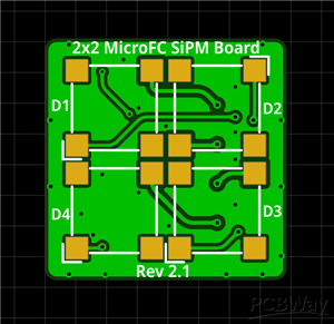
PCB size is 20 x 20 mm. The solder pads for the SiPM are slightly bigger than they need to so that you can easily hand-solder everything!
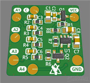
On the front side there are only the 4 sensors themselves while all the other parts are on the back. This ensures good optical contact and light-tight sealing. The PCB includes some bias filtering for the 4 SiPMs that must also be soldered and an optional temperature compensation circuit! The temperature compensation takes care of the change in bias voltage and therefore gain depending on the ambient temperature (~21mV/K).
If you want to use the added temperature compensation, be sure to solder all the components to the board and connect your power to the VCC pad. For setting the correct voltage, you can check the C pad on the PCB, but be sure to do this either before soldering the SiPMs or only when the SiPMs are not exposed to ANY light, otherwise they'll saturate immediately and pass a high current. You can also check the voltage on your power supply itself of course, but due to the nature of the compensation circuitry, the applied voltage to the SiPMs will then be a couple of 100 millivolts lower than what is shown. If you don't want to use the extra circuitry, you can apply your power directly to the C pad on the PCB. However, you still need to solder the low-pass filters for that (R2 - R5 and C2 - C5) and C1. The voltage will then be exactly what you apply.
The SiPMs all share a common cathode with bulk decoupling and an R-C low-pass filter each. The anodes are not connected together so that you can have some spatial resolution if you want to. You could mount a very small scintillator to each sensor and then have a four pixel gamma-ray camera, yay I guess?!
However, you can also connect all four SiPMs in parallel to a common output by connecting the anode pads to each other, e.g. by connecting the wires that you solder to the pads. You will obviously lose any spatial resolution, but this way you can use it just like a single SiPM in the 4P configuration. SNR should be pretty much the same as with a single SiPM, but your active area will be 4x that of a single one!
MicroFC-SiPM-Array-Board
*PCBWay community is a sharing platform. We are not responsible for any design issues and parameter issues (board thickness, surface finish, etc.) you choose.


Raspberry Pi 5 7 Inch Touch Screen IPS 1024x600 HD LCD HDMI-compatible Display for RPI 4B 3B+ OPI 5 AIDA64 PC Secondary Screen(Without Speaker)
BUY NOW


- Comments(0)
- Likes(1)
More by Matthias NuclearPhoenix
-
 MicroFC-SiPM-Array-Board
This is the affiliate page for the MicroFC SiPM Carrier Board.NOTE: THIS IS A 4 LAYER BOARD!You can ...
MicroFC-SiPM-Array-Board
This is the affiliate page for the MicroFC SiPM Carrier Board.NOTE: THIS IS A 4 LAYER BOARD!You can ...
-
 MicroFC SiPM Carrier Board
This is the affiliate page for the MicroFC SiPM Carrier Board.NOTE: THIS IS A 2 LAYER BOARD!You can ...
MicroFC SiPM Carrier Board
This is the affiliate page for the MicroFC SiPM Carrier Board.NOTE: THIS IS A 2 LAYER BOARD!You can ...
-
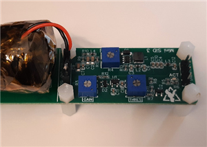 Mini SiPM Driver (Mini SiD) Board
Mini SiPM Driver (SiD) Board — Revision 4.xThis is the affiliate page for the Mini SiPM Driver (SiD)...
Mini SiPM Driver (Mini SiD) Board
Mini SiPM Driver (SiD) Board — Revision 4.xThis is the affiliate page for the Mini SiPM Driver (SiD)...
-
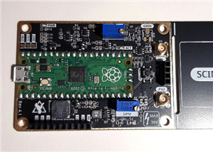 Open Gamma Detector
 — Revision 4.2 (Pico 2)This is the affiliate page for the Open Gamma Detector.NO...
Open Gamma Detector
Open Gamma Detector — Revision 4.2 (Pico 2)This is the affiliate page for the Open Gamma Detector.NO...
-
Programmable Mist Maker - XIAO / QT PY Extension
429 0 0 -
RadioHAT - Raspberry Pi radio development platform
331 0 1 -
-
-
-
-
ARPS-2 – Arduino-Compatible Robot Project Shield for Arduino UNO
2886 0 6 -
A Compact Charging Breakout Board For Waveshare ESP32-C3
3385 3 8 -
AI-driven LoRa & LLM-enabled Kiosk & Food Delivery System
3711 2 2


