


LoRaTube: Long-Life LoRa Repeater in a PVC Tube (No Lithium, No Solar)
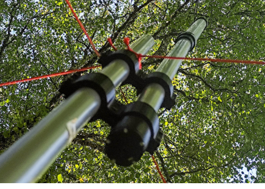
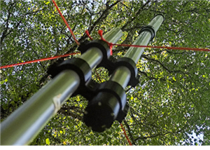
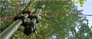
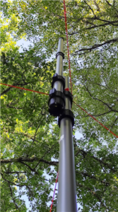
That’s why a repeater is necessary: to fully exploit the available link budget and reach long distances, the transmitter’s location must be carefully chosen. By placing the repeater at a high point — a hill, tower, or treetop with a clear line of sight — a single module can cover several tens of kilometers without exceeding the legally allowed transmission power. This strategy is at the heart of the LoRaTube concept: keeping a compliant, very low-cost, discreet, and autonomous transmitter (> 5 years), while maximizing coverage through optimal placement.
What We’re Proposing – Design Objectives
The goal is to build an ultra-discreet, robust LoRa repeater using widely available and very low-cost materials — specifically alkaline D-size (LR20) batteries and standard 40 mm / 50 mm PVC pipes for the enclosure and mast. The system is designed to run for multiple years in outdoor environments, including locations with no sunlight (under vegetation, in barns, etc.), for under €50 total, including the LoRa module and enclosure.
Note: This is version 1 of the device, and it is not yet final.
It provides around 2 months of autonomy, but it has already helped validate key design choices (mechanical layout, RF range, propagation testing).
A version 2 PCB is currently under development, with improved autonomy and resilience — including a watchdog, hardware timer, and complete shutdown of the Pico and buck converter between active phases.
Why LoRaTube?
Because this project does not use solar panels — it relies instead on alkaline batteries housed in a PVC tube. Most LoRa repeaters (whether DIY or commercial) depend on solar panels paired with lithium-ion batteries, MPPT regulators, and charge management circuitry.
This leads to:
a high cost (often €150 or more);
some mechanical and electronic fragility;
a bulky footprint, making the device more visible and attractive to theft;
and above all, poor reliability in winter: in temperate climates, solar production can drop fivefold between summer and winter, forcing designers to oversize the system just to maintain basic service.
🔋 Power Supply
The power supply is based on 18 LR20 alkaline batteries (D size) in series, housed in a compact enclosure less than 50 mm in diameter.
This battery choice offers several practical advantages: LR20 cells are inexpensive (less than €1 each in most supermarkets) and widely available. Each LR20 battery typically provides 12,000 to 18,000 mAh, or 18 to 27 Wh. With 18 batteries, the total energy amounts to approximately 486 Wh, for a total cost of €13.30 (5 packs × €2.66), which translates to just ~€0.024/Wh — a ridiculously low cost compared to lithium alternatives.
For comparison:
A 18650 lithium cell offers ~11 Wh for ~€4 → €0.36/Wh (15× more expensive)
A pack of ten flat lithium cells (~52 Wh) costs ~€20 → €0.38/Wh

Wiring 18 batteries in series raises the voltage to 27 V (18 × 1.5 V). The cost per delivered kilowatt-hour remains extremely competitive: around €13/kWh, compared to over €250/kWh for a solar + lithium setup (including MPPT regulator) — a 20× cost advantage.
These batteries also have very low self-discharge (< 1% per year), enabling several years of operation as long as the current draw stays low.
Another benefit: the batteries fit neatly inside a standard 40 mm PVC plumbing tube.
There’s just enough room for the LR20 cells and a return wire for GND — with an internal diameter of ~36 mm and the batteries themselves measuring ~33 mm.
Advantages:
- No exposed cables
- A sealed, rugged housing
- Fully weatherproof and mechanically robust
- A long, slim form factor that allows discreet installation in many environments: tree trunks, rooftops, wooden posts, etc.
- And in the event of a nuclear winter? You’ll be glad it runs on LR20s 😄
Preliminary question: can you be both a survivalist and environmentally conscious?

Using LR20 alkaline batteries may seem like an ecologically debatable choice — their main appeal lies in wide availability and an excellent €/kWh ratio. That said, the picture changes when you consider the following:
Producing 1 kWh of lithium battery capacity emits 150 to 200 kg of CO₂ (according to recent estimates).
Typical lithium extraction consumes ~1.9 million liters of water per ton, threatening local aquifers (e.g. the Lithium Triangle, Atacama Desert...).
By contrast:
LR20 batteries have a self-discharge of ≤ 2–3% per year and a storage life of 5+ years with minimal degradation.
In France, over 60% of alkaline batteries are recycled, while no effective recycling system exists yet for large-format lithium-ion batteries.
Advantages:
This is a simple, primary-chemistry solution (zinc and manganese). While not rechargeable, it offers very long field life and a low environmental impact per useful Wh, especially when yearly energy use is minimal.
The electrical design is also greatly simplified: no charge controller, no MPPT, fewer components — resulting in improved reliability and significantly lower cost.
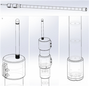
🛠️ Physical Architecture and Material Choices for a Standalone LoRa Repeater
🧰 Mechanics

The mechanical structure is based on a standard 40 mm PVC drainage pipe, whose internal diameter (~36 mm) perfectly fits an LR20 battery and wiring. This clever choice takes advantage of PVC’s strength, availability, and low cost, and minimizes the need for custom 3D-printed parts.

The 3D-printed components are grouped into three functional modules, requiring about 120 g of PLA in total:
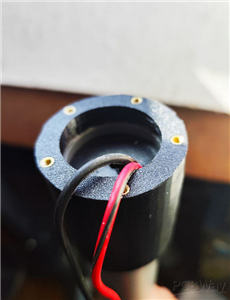
- The tube base, which provides access to the batteries for replacement and ensures contact with the negative terminal of the first battery in the 18-cell series. To avoid mechanical stress, the usual spring is replaced by a brass strip simply soldered to a wire.

2. The compression mechanism, which keeps the battery stack under pressure using three springs and two cylindrical PLA parts. The springs exert around 1 kg of force over 6 mm of travel, with a maximum travel of approximately 15 mm. An M3 screw, whose head moves freely in the upper part and locks with a nut at the bottom, ensures the whole assembly stays in place — even when the system is not under compression.


3. The intermediate part, which makes contact with the positive terminal of the topmost battery and acts as an axial stop to keep the battery stack compressed. Small vent holes at the bottom allow any condensation or water ingress to escape.


4. The top cap, which mechanically supports the PCB via the SMA connector, holds the antenna, and ensures the system is sealed.
It fits onto the top end of the 50 mm diameter PVC tube.


⚡ Energy Considerations
Internal Resistance
Using LR20 alkaline batteries in series adds up their individual internal resistances.
A fresh LR20 cell typically has an internal resistance of about 0.13 to 0.17 Ω.
With 18 batteries in series, the total internal resistance becomes roughly 18 × 0.15 Ω ≈ 2.7 Ω.
Under load, this causes a voltage drop:
At 110 mA (typical transmission with an E22400T22D module), the drop is
ΔV = I × R ≈ 0.11 × 2.7 ≈ 0.30 V
At 1.3 A (typical for E22400T33D),
ΔV ≈ 1.3 × 2.7 ≈ 3.5 V
These voltage drops reduce the effective input voltage available to the system.
Fortunately, in both cases, there’s still a comfortable margin for the buck converter, which only needs to step down to 5 V.
Actual Current Draw from the Batteries
Both the E22400T22D and E22400T33D modules are powered through a DC/DC buck converter (≈85% efficiency).
Assuming an input bus voltage of ~23 V (after subtracting internal drops from the 27 V nominal), the current drawn from the battery pack is:
E22400T22D (TX at 22 dBm):
~110 mA at 5 V → 0.55 W output
⇒ Input current ≈ 27 mA
E22400T33D (TX at 33 dBm):
~1.0 A at 5 V (values between 850 mA and 1200 mA depending on datasheet)
→ ~5 W output
⇒ Input current ≈ 242 mA

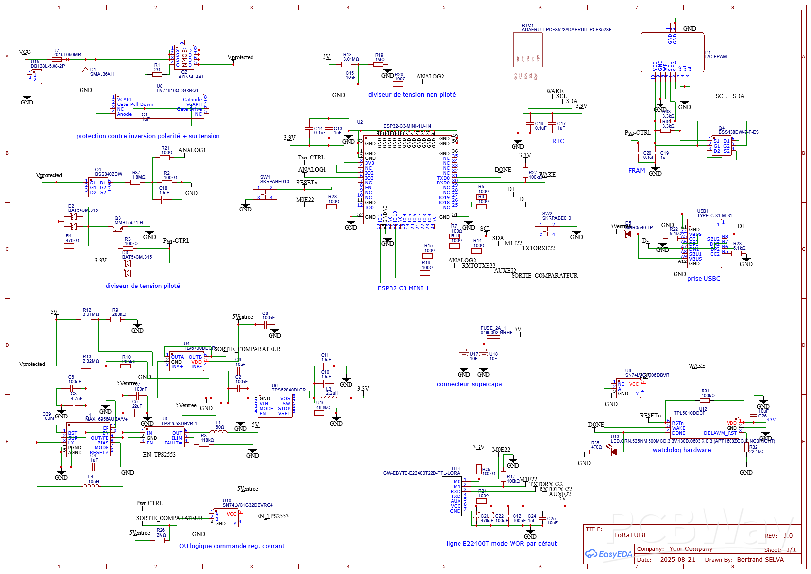
Electronic


The power path starts from a 20–30 V pack of alkaline batteries. The input is protected against reverse polarity and surges by an LM74610 ideal diode and a TVS diode (SMAJ36AH). A MAX16956 buck converter then provides a regulated 5 V rail, always on.
On this 5 V line sits a TPS2553 current limiter, set to about 250 mA (R_ILIM ≈ 118 kΩ). This limiter is mandatory because the supercapacitors are placed after it, directly on the 5 V bus.
During LoRa TX bursts, the E22-400T33D can draw up to 1.3 A. Thanks to their low ESR, the supercaps deliver this current. But when they recharge, the limiter ensures the source current stays below 250 mA (~70 mA on the battery side).
This low recharge current is critical: it is compatible with end-of-life alkaline packs or very cold conditions, and it even improves autonomy—lower current means more usable energy can be extracted from the cells.
The supercap charging is supervised by a TLV6700 comparator (previously a MAX8212 in V1). It cuts charging at 4.90 V and re-enables it below 4.75 V, stabilizing the bus around 4.8 V. This is high enough for reliable E22 operation but low enough to minimize supercap leakage, which increases with voltage and temperature.
From this 5 V rail, a TPS62840 ultra-low Iq buck generates the permanent 3.3 V rail. This powers the ESP32-C3, the TPL5010 watchdog, the PCF8523 RTC, and the FRAM memory.
The RTC is always powered, mainly to use its alarm output, wired together with the TPL5010 WAKE through an open-drain buffer.
The FRAM (≈ 27 µA continuous consumption) is physically disconnected when not logging, using MOSFET switches to avoid phantom powering through the I²C bus.
Two high-impedance resistor dividers allow monitoring of both the input (30 V) and the 5 V bus. The high-voltage divider is switched by a P-MOS/NPN combo for ESP32 safety.
The LoRa E22 module runs directly from the supercap 5 V bus. The ESP32 supervises the radio: if the module becomes unresponsive, a hard reset circuit can force recovery (still pending in this version).
The watchdog (TPL5010) resets the ESP32 if it fails to toggle DONE within 10 s. The firmware kicks it every 8 s, and the DONE line also drives a small green LED, flashing 100 ms every cycle—visible but still energy-friendly.
Protections are layered:
SMAJ36AH TVS for surge,
Polyfuse 2016L050MR set at 500 mA for the input,
LM74610QDGKRQ1 ideal diode for reverse polarity and blocking back-feed to the cells,
2 A fuse on the supercap path.
Finally, a USB-C connector allows ESP32 programming and log extraction. Two tactile switches let you force BOOT mode or reset, just like on a standard devkit.
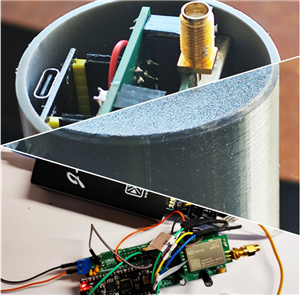
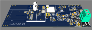
PCB
There have been two versions of the PCB. The first one, with a battery life of around two months, was designed mainly for initial propagation tests (see video) as well as to check weather resistance.
Version 2 is currently being manufactured and follows the schematic shown above. You can find the Gerber files in the links.

LoRaTube: Long-Life LoRa Repeater in a PVC Tube (No Lithium, No Solar)
*Due to unresolved design issues with this PCB, orders cannot be placed at this time. We appreciate your understanding.


Raspberry Pi 5 7 Inch Touch Screen IPS 1024x600 HD LCD HDMI-compatible Display for RPI 4B 3B+ OPI 5 AIDA64 PC Secondary Screen(Without Speaker)
BUY NOW


- Comments(5)
- Likes(2)
- 1 USER VOTES
- YOUR VOTE 0.00 0.00

-
10design
-
9usability
-
10creativity
-
10content
More by Engineer
-
Programmable Mist Maker - XIAO / QT PY Extension
233 0 0 -
RadioHAT - Raspberry Pi radio development platform
256 0 1 -
-
-
-
-
ARPS-2 – Arduino-Compatible Robot Project Shield for Arduino UNO
2813 0 6 -
A Compact Charging Breakout Board For Waveshare ESP32-C3
3315 3 8 -
AI-driven LoRa & LLM-enabled Kiosk & Food Delivery System
3600 2 2


