


|
Altium DesignerAltium Designer
|
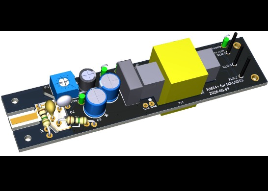
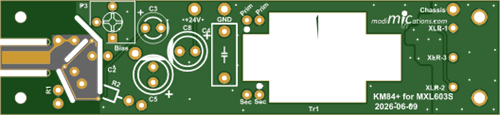
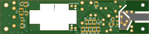
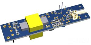
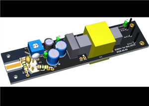
KM84+ for MXL603 SDC Microphone
EDIT 2026-06-08: I have updated C5 and C8 in the BOM. They have changed to 47uF/35V E-Caps. The diameter of these caps is 6.3 mm, whereas the 4.7uF caps were 5 mm. These 6.3mm caps will fit on the board as is, but I'll change the Gerber files later, showing the right diameter in silkscreen print. Theoretically, the 47uF will reduce Zener noise better, but I'm not sure whether this will actually be audible.
EDIT 2026-06-10: Updated Gerber files uploaded with larger-diameter C5 and C8 silkscreen print.
The vintage Neumann KM84 is a popular microphone to build because of its legendary status and simple circuitry. However, the design has a disadvantage that some find annoying: It is susceptible to cell phone interference. This design pays extra attention to suppressing this interference. For a detailed circuit description, please refer to the references at the bottom of this building instruction. I would strongly recommend reading these articles first if you want to deviate from the enclosed BOM.
This PCB was specifically designed for the MXL603 and MXL991, and possibly other similarly sized MXL microphones.
This PCBA uses mainly SMT components because this is the only way to get good working cell phone interference suppression. It also solves the problem of the increasingly scarce availability of good JFETs. I have used as many "large", DIY-friendly SMTs as possible. However, if you are apprehensive about soldering these, consider using the PCBWay Assembly service. And solder the wired components yourself. For components you might want to experiment with, I have used wired components where possible. E.g., if you want to add some fancy colors to your build because of the looks, consider replacing the E-caps C3, C5 and C8 with red Würth Elektronik Polymer Caps, type 870055673001. These are 10uF instead of 4.7uF, but that doesn't matter at all.
Before we get into the assembly instructions, let's first briefly talk about component selection.
If you don't know which transformer to use, I would like to refer you to the KM84 circuit description, the link to which is listed under references. Don’t ask me which one sounds best: I have only used the ASTDS T-8 and 3U Audio versions. The 3U seems to have some more bottom end and would be my preference of the two.
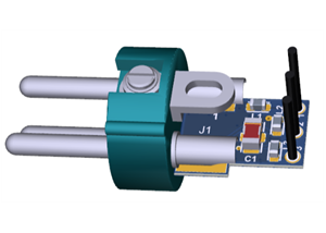
Unfortunately, the XLR insert that is in the BOM and offers the best RFI suppression is only available per 100 pieces. Regular ones, like these, can be used, but you want to solder a short wire between the Chassis solder pad next to Pin 1 to the brass tail part of the microphone for best RFI rejection. I'm afraid XLR inserts with a wing-shaped ground tab will not fit inside the tail part, though I have not checked.
The BOM contains a mix of multiple manufacturers of SMT resistors. You can use any manufacturer of Thick-film resistors that Mouser or Digikey offers, as long as you keep the same value and tolerance. There is absolutely no point in using precision Thin-Film resistors. Do not expect a better sound quality or less noise from such resistors. The low noise of Thin-Film resistors only applies to the so-called excess noise, or 1/f noise, which only occurs at very low frequencies, to which our hearing has a very low sensitivity. The thermal (Johnson) noise is the same for all resistors. Only for R9 and R10, you’ll want to use precision 0.1% resistors, but they are also available as Thick-Film. Alternatively, from a batch of 2k2 1% resistors, select a pair of resistors that match within 0.1% for the best CMRR (i.e. best mains hum rejection).
The same goes for the capacitors: you can use other brands as long as you follow the Description when selecting the components. For capacitors in the audio path, you want to use C0G/NP0 ceramic capacitors, film, or good-quality electrolytic capacitors. I have no reason to believe that special audio capacitors lead to better sound quality, other than caused by the placebo effect. But everyone has their own opinion on this, and if you think that other types than those listed give a better result, feel free to experiment with them.
There is no need to select the JFET because the bias current can be adjusted through a trimmer potmeter. It is not likely, but also not impossible, that the gains of two JFETs from one reel differ so much that the gains of two PCBAs differ by more than 0.5 dB.
For the nose cone, you should use the one from the stock PCBA. I currently don't have a 3D printable model available. If you want to design one yourself, then have a look here for some inspiration: https://www.pcbway.com/project/shareproject/Takstar_CM_60_and_CM_63_nose_cone_272ff5ee.html
Assembly Instructions:
If you are not experienced in soldering SMT components, consider ordering the PCBA with the SMT components already assembled by PCBWay. I have provided the Centroid pick-and-place file listing all the SMT components. The BOM contains all parts on the PCBA. If you want to deviate from the standard BOM, provide your own to PCBWay to follow when building the PCBA(s).
Solder the SMT parts from small to big. Solder the JFET as the last component.
Solder the through-hole parts.
Solder the transformer to the PCBA. You may want to cut the excess length of the transformer leads. The primary side connections are marked on the PCB with Prim and the secondary side with Sec. The start of the winding is indicated with a dot. Your transformer datasheet should provide this information.
Near the XLR insert, there is a Chassis ground connection. If your solder iron has enough power to solder a wire to the mic body tail part, you can solder a wire from here to the tail part for improved RFI rejection.
Connect the PCBA to a P48 Phantom power supply, mixer or preamp. Connect a voltmeter between the ground and Bias test terminals. Wait ~1 minute for the bias current to settle. Adjust P3 until the Bias voltage reads ~11V. The original KM84 should be adjusted to 10V, but in this circuit, the JFET stage operates from a slightly higher supply voltage for more headroom and should be adjusted to 11V.
Alternatively, use a good-quality Audio Interface and REW to adjust P3 until the lowest THD is obtained or symmetrical clipping is achieved. The output signal from the Audio Interface is fed to the input terminal through a 39pF capacitor. The problem with this procedure is that the PCBA has to be placed in a Faraday cage while adjusting, because mains hum will interfere with your measurements. Use whatever method that suits you best…
Clean the PCBA with Isopropyl Alcohol. At least the area with the JFET and GOhm resistors must be cleaned thoroughly. Apply IPA, then clean with a brush, and finally rinse with IPA again. Dry with a heat gun or hair dryer.
Assemble the complete microphone. After assembly has been completed, you should perform a polarity check to ensure you have not accidentally swapped the transformer wires. I will describe more methods on my website, but one simple way is to have a known-good mic and your DIY mic hooked up to a mixer. Speak into one mic at a time and adjust the gain until you hear both mics at an equal level through the headphone monitoring output. Then keep both mics next to each other and speak into both mics. The level should now be louder than when speaking into one mic. If it is softer, the polarity of your DIY mic must be inverted by swapping the wires on either the primary or secondary side of the transformer.
Enjoy your DIY KM84 microphone!
References:
KM84 Circuit Description: https://modimications.com/km84-style-charge-amplifier-circuit/
KM84+ Circuit Description: https://modimications.com/km84-and-km84-head-amp-circuits/
GroupDIY thread that led to this design: https://groupdiy.com/threads/is-there-a-way-to-reduce-cell-phone-interference-in-diy-km-84.86707/
KM-84 Clone – Blind Test thread: https://groupdiy.com/threads/four-km-84-clones-blind-test.89135/
List of other microphone PCBs: https://modimications.com/all-orderable-pcbs/
KM84+ for MXL603 SDC Microphone
*PCBWay community is a sharing platform. We are not responsible for any design issues and parameter issues (board thickness, surface finish, etc.) you choose.


Raspberry Pi 5 7 Inch Touch Screen IPS 1024x600 HD LCD HDMI-compatible Display for RPI 4B 3B+ OPI 5 AIDA64 PC Secondary Screen(Without Speaker)
BUY NOW


- Comments(0)
- Likes(1)
More by Jan Postma
-
 Condenser Microphone RFI Filter
This little PCB contains an RF Interference filter that has been optimised to suppress cell phone in...
Condenser Microphone RFI Filter
This little PCB contains an RF Interference filter that has been optimised to suppress cell phone in...
-
 Takstar CM-60 and CM-63 nose cone
For this nose cone design, you will need to acquire the following parts:This Nose Cone.4 mm outside,...
Takstar CM-60 and CM-63 nose cone
For this nose cone design, you will need to acquire the following parts:This Nose Cone.4 mm outside,...
-
 KM84+ for MXL603 SDC Microphone
EDIT 2026-06-08: I have updated C5 and C8 in the BOM. They have changed to 47uF/35V E-Caps. The diam...
KM84+ for MXL603 SDC Microphone
EDIT 2026-06-08: I have updated C5 and C8 in the BOM. They have changed to 47uF/35V E-Caps. The diam...
-
 KM84++ for Takstar CM-63 Microphone
Before going into the project details, an important note: when you order the PCB, choose a thickness...
KM84++ for Takstar CM-63 Microphone
Before going into the project details, an important note: when you order the PCB, choose a thickness...
-
 Slide switch knob for Takstar CM-60 compatible DIY PCBA builds
This slide switch knob can be used for DIY PCBAs that fit the Takstar CM-60 condenser microphone. If...
Slide switch knob for Takstar CM-60 compatible DIY PCBA builds
This slide switch knob can be used for DIY PCBAs that fit the Takstar CM-60 condenser microphone. If...
-
 KM84+ for Takstar CM-60
Before going into the project details, an important note: when you order the PCB, choose a thickness...
KM84+ for Takstar CM-60
Before going into the project details, an important note: when you order the PCB, choose a thickness...
-
Programmable Mist Maker - XIAO / QT PY Extension
805 1 0 -
RadioHAT - Raspberry Pi radio development platform
648 0 1 -
-
-
-
-
ARPS-2 – Arduino-Compatible Robot Project Shield for Arduino UNO
3113 0 6 -
A Compact Charging Breakout Board For Waveshare ESP32-C3
3734 3 8 -
AI-driven LoRa & LLM-enabled Kiosk & Food Delivery System
4058 2 2


