


High Power LED Board
Hey what's up you guys, this is a HIGH POWER LED BOARD that I made completely from scratch.
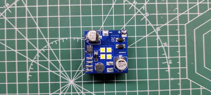
It consists of Four XPLAWT LEDs that are High-Intensity LEDs each rated for 3A Max and their operating Voltage is 2.8V to 3.2V.
Cree Makes these High Power LEDs and you can read its datasheet for more info- https://www.mouser.in/datasheet/2/723/ds_XPL-2327187.pdf
As for driving the HIGH Power LEDs, an LED Driver IC was used.
Why LED Drivers are used?
An LED could be easily powered through any DC source but what if you want a regulated source that can control the current going to LED, in such case an LED Driver is required.
Also, directly powering an LED through any power source might kill the LED as LEDs have a tendency to take as much current as they can have and this usually fries the LED from the inside. LED Driver limits the current taken by LED and regulates the whole system in a linear way, Current is also controlled when the temperature gets too hot.
Here's another reason, LED Driver can be connected to an external microcontroller setup and we can control them easily by providing them PWM Signal for dimming or ON-OFF control.
Here's a nice article about this topic- https://www.meanwell.com/newsInfo.aspx?c=5&i=1061#:~:text=Currently%2C%20many%20low%2D%20and%20medium,number%20of%20LEDs%20in%20parallel.
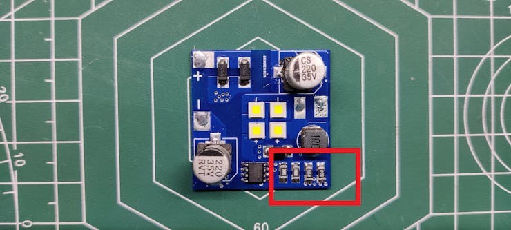
SIC9301A LED Drive IC is used in this build, it's an LED Driver IC that is rated up to 10W of power and we can easily control or set the output power of the LED by changing the value of resistors on the board.
Material Required
following are the materials used in this built-
- SIC9301A
- Custom PCB
- 1R0 Resistor 1206 Package
- R470 Resistor 1206 Package
- SS34 Diode SMA Package
- 100uF 25V Capacitor
- 1uH Inductor
- 12V battery for power
Schematic
_j2SLC8v55O.jpg?auto=compress%2Cformat&w=740&h=555&fit=max)
Here's the schematic that we have used and it's a simple one.
We connect four XPLAWT LEDs in series, each LED requires 2.8V min so four in series would at least require 11.2V for operation.
These LEDs are connected with the SIC9301 LED Driver output side, SIC9301 is configured according to its datasheet layout.
PCB Design
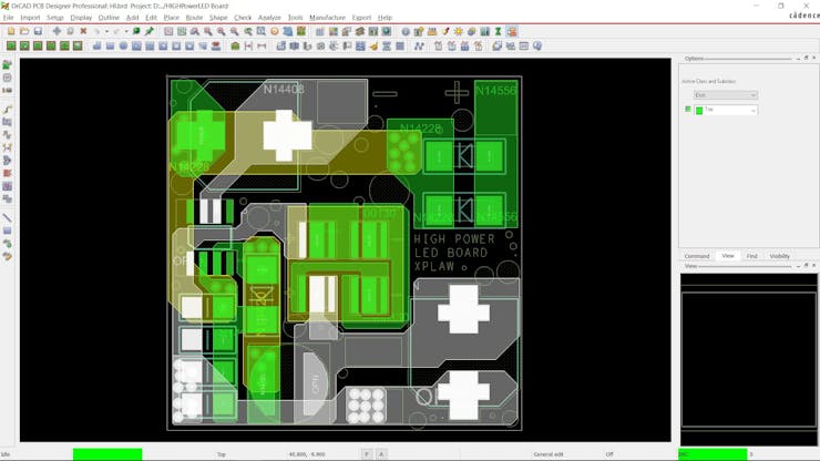
After completing the Schematic, we export the netlist and convert the schematic into a board file.
I prepared a 34x34 outline and place the LEDs at the center of the board.
Because this was an LED Driver board, it was wiser to use wide shape tracks instead of using regular 1mm tracks.
Also, to make this setup easy to build, I use all SMD components in this build, from capacitors to inductors all are surface mount devices.
PCBWAY


After finalizing the board, I exported the Gerber Data and sent it to PCBWAY for samples.
A Blue solder mask and white silkscreen was used for this project.
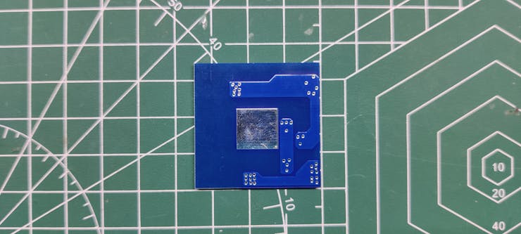
I received PCBs in a week and the PCBs were nice as expected.
I really like the quality of the Blue solder mask, PCBWAY did an excellent job of manufacturing this PCB with no error whatsoever.
check out PCBWay service for getting great PCB service at less cost.
Solderpaste Dispensing Process

We apply solder paste with a solder paste dispenser syringe or the proper method is to use stencil here which I don't have. but anyway, after this, we can now move on to the next process, which is to add components to each pad.
Pick and Place Process

Next, we carefully pick all the components with an ESD tweezer and place them in their assigned place one by one.
We start first by placing Capacitors, Diodes, and resistors.
Next, we add LEDs in their place, we make sure to place LEDs in the right position.
Hotplate Reflow Process


Then after doing the pick and place process, we carefully lifted the whole PCB and place it on the hotplate. I’m using my good old DIY hotplate which I made a few months ago.
Basically, in this hotplate reflow process, the surface heats up to the solder paste melting temp and it slowly melts. after a few mins when the solder paste completely melts, we remove the PCB and let it cool down for a moment.
Testing


We connect a 12V battery source with the LED Board in order to test the setup by measuring its voltage across the input side and the current drawn by the LED Board.
For Measuring the Current, I set up a multimeter in current mode and connected the probes in series with the LED Board.
For Measuring Voltage, we connect probes of the multimeter with the input side of the LED Board, observed voltage is 11.52V.
Current is fluctuating and can be seen increasing, it started at 0.445A but increased up to 0.470A as time progresses.
This is happening because of the LED Drover, To keep driving LED at constant power, Voltage gets decreased and current increases this causes stable power output that is maintained for a duration of time until the battery run out of JUICE.
The power of this whole LED Board is 11.52V x 0.470A which is - 5.4W.
Similarly, we can calculate the output power by measuring LED Current and LED Voltage and then calculate efficiency by dividing Input Power by output power.
Adding Heatsink


After testing the board, we add a heatsink with this board for dissipating heat and making this setup optimal to use, after all, it's a 6W LED Board that obviously generates heat because of the HIGH Power LED it uses.
- We start by first placing the Double-sided thermal Tape on the heatsink and then removing its top cover.
- Next, we place LED Board on the heatsink and press the board evenly onto the heatsink so the tape will hold the board in its place.
RESULT
Here's the result of this small built, working HIGH-Intensity LED Board that operates at a power of 6W and is super bright.
Further Scope
This PCB is just 34mm x 34mm in size and is very compact, meaning it's ideal for some handy use.
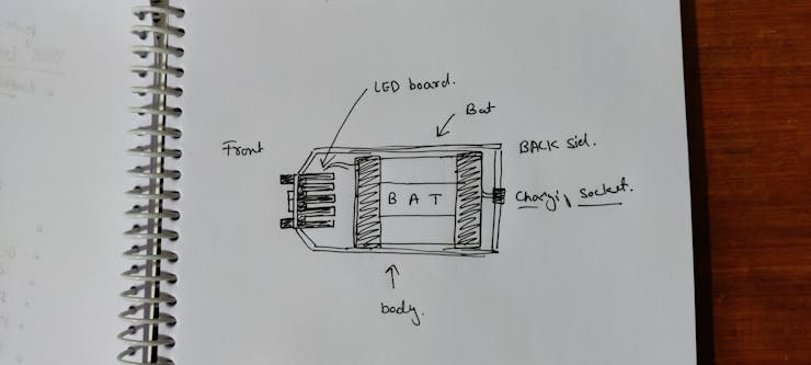
The main goal behind preparing this project was to prepare a High Power Mag Light, for making a Mag light we needed a high-intensity light source so I prepared this board.
The next Project will utilize this High power LED board for preparing a Mag Light with decent backup and high Lux.
Special thanks to PCBWAY for supporting this project, do check them out for getting great PCB Service for less cost.
Until then, stay tuned.

High Power LED Board
*PCBWay community is a sharing platform. We are not responsible for any design issues and parameter issues (board thickness, surface finish, etc.) you choose.


Raspberry Pi 5 7 Inch Touch Screen IPS 1024x600 HD LCD HDMI-compatible Display for RPI 4B 3B+ OPI 5 AIDA64 PC Secondary Screen(Without Speaker)
BUY NOW


- Comments(0)
- Likes(1)
More by Arnov Arnov sharma
-
 DIY XBOX Controller
Greetings everyone, and welcome back. Here's something fun and custom.This is my version of an Xbox ...
DIY XBOX Controller
Greetings everyone, and welcome back. Here's something fun and custom.This is my version of an Xbox ...
-
 Pocket SNES
Greetings everyone, and welcome back! Today, I’ve got something fun and tiny to share—the Pocket SNE...
Pocket SNES
Greetings everyone, and welcome back! Today, I’ve got something fun and tiny to share—the Pocket SNE...
-
 Batocera Arcade Box
Greetings everyone and welcome back, Here's something. Fun and nostalgic. Right now, we are using ou...
Batocera Arcade Box
Greetings everyone and welcome back, Here's something. Fun and nostalgic. Right now, we are using ou...
-
 64x32 Matrix Panel Setup with PICO 2
Greetings everyone and welcome back.So here's something fun and useful: a Raspberry Pi Pico 2-powere...
64x32 Matrix Panel Setup with PICO 2
Greetings everyone and welcome back.So here's something fun and useful: a Raspberry Pi Pico 2-powere...
-
 Portable Air Quality Meter
Hello everyone, and welcome back! Today, I have something incredibly useful for you—a Portable Air Q...
Portable Air Quality Meter
Hello everyone, and welcome back! Today, I have something incredibly useful for you—a Portable Air Q...
-
 WALKPi PCB Version
Greetings everyone and welcome back, This is the WalkPi, a homebrew audio player that plays music fr...
WALKPi PCB Version
Greetings everyone and welcome back, This is the WalkPi, a homebrew audio player that plays music fr...
-
 Delete Button XL
Greetings everyone and welcome back, and here's something fun and useful.In essence, the Delete Butt...
Delete Button XL
Greetings everyone and welcome back, and here's something fun and useful.In essence, the Delete Butt...
-
 Arduino Retro Game Controller
Greetings everyone and welcome back. Here's something fun.The Arduino Retro Game Controller was buil...
Arduino Retro Game Controller
Greetings everyone and welcome back. Here's something fun.The Arduino Retro Game Controller was buil...
-
 Super Power Buck Converter
Greetings everyone and welcome back!Here's something powerful, The SUPER POWER BUCK CONVERTER BOARD ...
Super Power Buck Converter
Greetings everyone and welcome back!Here's something powerful, The SUPER POWER BUCK CONVERTER BOARD ...
-
 Pocket Temp Meter
Greetings and welcome back.So here's something portable and useful: the Pocket TEMP Meter project.As...
Pocket Temp Meter
Greetings and welcome back.So here's something portable and useful: the Pocket TEMP Meter project.As...
-
 Pico Powered DC Fan Driver
Hello everyone and welcome back.So here's something cool: a 5V to 12V DC motor driver based around a...
Pico Powered DC Fan Driver
Hello everyone and welcome back.So here's something cool: a 5V to 12V DC motor driver based around a...
-
 Mini Solar Light Project with a Twist
Greetings.This is the Cube Light, a Small and compact cube-shaped emergency solar light that boasts ...
Mini Solar Light Project with a Twist
Greetings.This is the Cube Light, a Small and compact cube-shaped emergency solar light that boasts ...
-
 PALPi V5 Handheld Retro Game Console
Hey, Guys what's up?So this is PALPi which is a Raspberry Pi Zero W Based Handheld Retro Game Consol...
PALPi V5 Handheld Retro Game Console
Hey, Guys what's up?So this is PALPi which is a Raspberry Pi Zero W Based Handheld Retro Game Consol...
-
 DIY Thermometer with TTGO T Display and DS18B20
Greetings.So this is the DIY Thermometer made entirely from scratch using a TTGO T display board and...
DIY Thermometer with TTGO T Display and DS18B20
Greetings.So this is the DIY Thermometer made entirely from scratch using a TTGO T display board and...
-
 Motion Trigger Circuit with and without Microcontroller
GreetingsHere's a tutorial on how to use an HC-SR505 PIR Module with and without a microcontroller t...
Motion Trigger Circuit with and without Microcontroller
GreetingsHere's a tutorial on how to use an HC-SR505 PIR Module with and without a microcontroller t...
-
 Motor Driver Board Atmega328PU and HC01
Hey, what's up folks here's something super cool and useful if you're making a basic Robot Setup, A ...
Motor Driver Board Atmega328PU and HC01
Hey, what's up folks here's something super cool and useful if you're making a basic Robot Setup, A ...
-
 Power Block
Hey Everyone what's up!So this is Power block, a DIY UPS that can be used to power a bunch of 5V Ope...
Power Block
Hey Everyone what's up!So this is Power block, a DIY UPS that can be used to power a bunch of 5V Ope...
-
 Goku PCB Badge V2
Hey everyone what's up!So here's something SUPER cool, A PCB Board themed after Goku from Dragon Bal...
Goku PCB Badge V2
Hey everyone what's up!So here's something SUPER cool, A PCB Board themed after Goku from Dragon Bal...
-
Programmable Mist Maker - XIAO / QT PY Extension
172 0 0 -
RadioHAT - Raspberry Pi radio development platform
182 0 1 -
-
-
-
-
ARPS-2 – Arduino-Compatible Robot Project Shield for Arduino UNO
2767 0 5 -
A Compact Charging Breakout Board For Waveshare ESP32-C3
3275 3 8 -
AI-driven LoRa & LLM-enabled Kiosk & Food Delivery System
3530 2 2


