



|
Hot PlateGeneric
|
|

|
SMT Solder Paste SqueegeeGeneric
|
|

|
KiCad 9.0 |
|

|
Soldering iron (generic) |
G-EDM Gapstorm Pro Pulseboard
G-EDM Gapstorm Pro
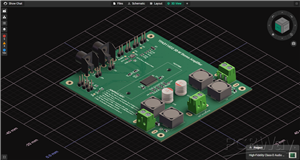
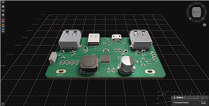
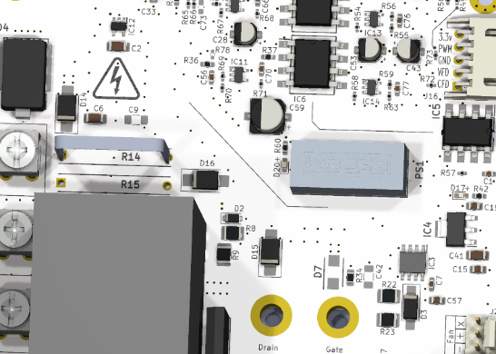
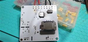
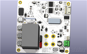
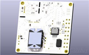
Warning: The board is able to carry significant currents and there are two components that require a cooling solution. The Mosfet requires a heatsink. it can be screwed without isolation barrier to a heatsink. The Mosfets exposed metal body is not internally connected and isolation is not needed. Thermal paste should be placed between the FET and the Heatsink. But also the big freewheeling diode (STTH60RQ06L2Y) requires cooling. It is not the same height as the Mosfet so there needs to be a little metal pad to fill the space between diode and heatsink. The diode exposed metal cover is internally connected and therefore a little isolation pad is required between the diode and the shimming block. If for some reason it is not possible to cool the diode it would also be ok to just remove it.
DIY EDM has made significant progress, and so has the G-EDM.
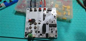
After months of tinkering and testing, I’m excited to introduce the improved Gapstorm Pro - an evolution of the original Gapstorm Pulseboard.
This new version not only reduces component costs but also enhances circuit performance where possible.
In the initial design, a 10Ω resistor was used in the gate drive circuit, which was too fast and risked burning the MOSFET if the current exceeded approximately 3A. To address this, I replaced the gate resistor with a 100Ω (2.5W) resistor. This adjustment allowed me to build a test setup capable of handling over 9A, limited by the DPH8909 PSU.
For testing, I used two parallel IRFP260N MOSFETs instead of the expensive SOT227 FET the board is designed for.
To avoid risking the precious FET that is required to actually work on the firmware I will stick to the above test for now and not try to replicate it with the big FET.
Based on experience, I am confident that the SOT227 FET can handle the same currents without issues.
Note about the SOT227 Mosfet:
The Mosfet included in the BoM comes in a big SOT227 package and can be mounted directly onto a heatsink or a metal enclosure without an isolation barrier required. Just a little cooling paste. But it is an expensive FET. The PCB has Through Hole Screw Pads to mount the FET Terminals onto the board directly. Those terminals can also be used to connect all kind of different FETs. One way would be to use two parallel IRFP260N (for low currents even a single one can work well) and connect them with wires to the PCB Terminal pads. This would already reduce total component costs by $40.- People who are good at soldering may want to source the THT components on their own and manually solder them to save even more.
The Gapstorm Pro features a default 100Ω gate resistor to keep inrush current under control, but several other enhancements to boost performance have been incorporated as well.
A flyback diode across the MOSFET ensures cleaner switching behavior, while TVS diodes protect against voltage spikes. Additionally, an RC snubber is included to improve switching characteristics.
The TVS diodes have an 85V working voltage, ensuring they remain non-conductive up to that point. For safety and reliability, I recommend to keep the voltage below 80V.
Furthermore, the costly SOIC8 op-amps have been replaced with smaller, more affordable variants that offer improved performance.
To enhance spark quality, a 70μF foil capacitor has been added, delivering a sharper, more intense spark.
Overall, the Gapstorm Pro represents a significant step forward in DIY EDM technology:
more efficient, more affordable, and more reliable.
Recommended Board configuration:
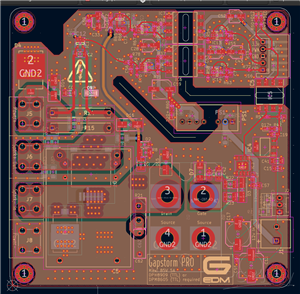
2mm PCB thickness (1.6mm will work too but 2mm provides a little extra clearance between layers and feels better)
1oz/in copper for all 4 layers
Layer order from top to bottom:
gapstorm-retro-F_Cu.gbr
gapstorm-retro-In1_Cu.gbr
gapstorm-retro-In2_Cu.gbr
gapstorm-retro-B_Cu.gbr
For more details, including the KiCAD files, please visit the Github repo:
https://github.com/G-EDM/Gapstorm-Pro
G-EDM Gapstorm Pro Pulseboard
Project images are for reference only. Actual production is based on the manufacturing files on the project page.
Please review the designer's notes (e.g., PCB thickness) and select the appropriate options.
PCBWay is not responsible
for issues caused by unsuitable parameter selections.
For more important ordering information, please refer to
Read More


Raspberry Pi 5 7 Inch Touch Screen IPS 1024x600 HD LCD HDMI-compatible Display for RPI 4B 3B+ OPI 5 AIDA64 PC Secondary Screen(Without Speaker)
BUY NOW


- Comments(0)
- Likes(0)
More by Roland Lautensack
-
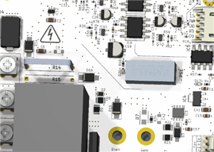 G-EDM Gapstorm Pro Pulseboard
G-EDM Gapstorm ProWarning: The board is able to carry significant currents and there are two compone...
-
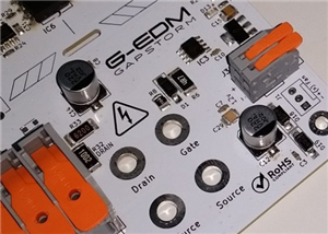 G-EDM Gapstorm Pulseboard (deprecated)
Outdated! Link to the new Gapstorm Pro board:Please order the new Gapstorm Pro board instead of this...
-
 G-EDM EVOIII Motionboard
https://gedm.org/This board comes with a more thoughtful placement of all th...
-
 G-EDM Motionboard
Note from PCBWay: This page only includes the motionboard. To build the G-EDM it also requires the p...
-
-
AudioLink – USB & Bluetooth LE Audio / Auracast Receiver with Balanced Line Outputs (nRF5340)
141 0 0 -
-
-
-
Émetteur Récepteur Optique Expérimental (communication UART ATtiny + fibre optique)
314 0 1 -
SmallOLED - Live PC Stats, Animated Clocks & Audio Visualizer
1314 0 3 -
"Talking Multimeter": Arduino-Based Speech Add-on for Multimeters with SCPI Protocol
747 0 1 -
Programmable Mist Maker - XIAO / QT PY Extension
3281 2 4