

|
KiCad 9.0 |
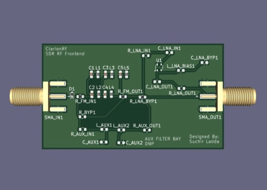
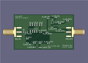
ClarionRF_V1
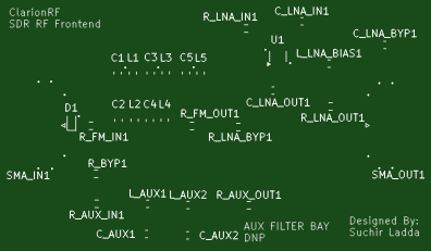
ClarionRF is a modular RF frontend PCB designed for SDR-based passive radar and spectrum analysis experiments. The board was created as a practical RF hardware platform that sits between an antenna and an RTL-SDR or similar software-defined radio. The goal was to design something more useful than a simple FM filter board: ClarionRF includes ESD protection, a selectable FM bandpass filter path, a bypass path, an auxiliary future filter bay, and an optional LNA stage.
The main use case is passive radar using FM broadcast towers as illuminators of opportunity. In a future two-SDR setup, one SDR can receive the direct reference signal from an FM transmitter while another receives reflections from moving objects through a surveillance antenna. ClarionRF is designed to clean up the RF input before it reaches the SDR by filtering for the 88–108 MHz FM broadcast band, which is commonly used in passive radar experiments.
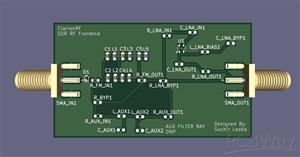
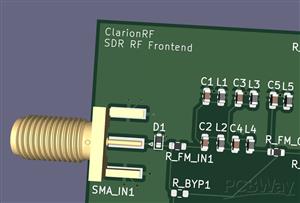
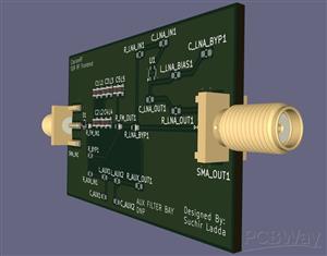
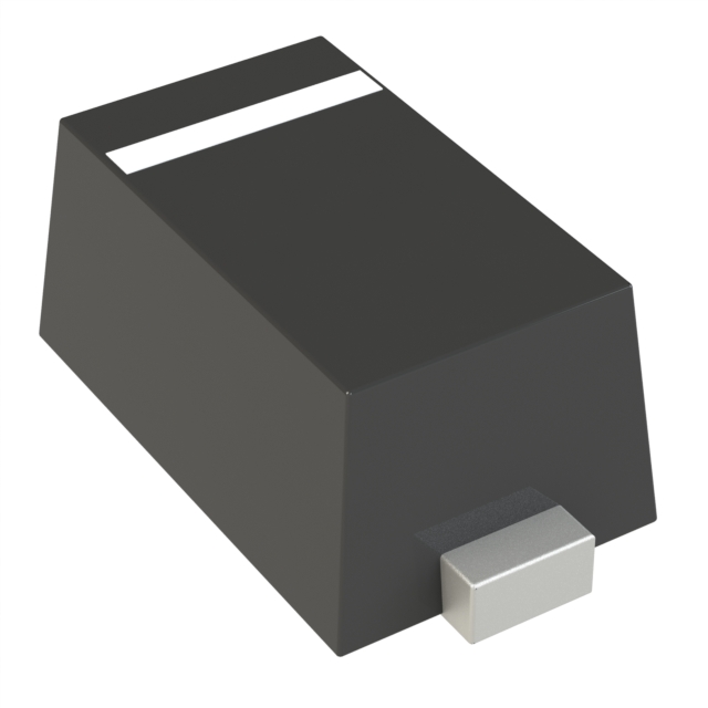
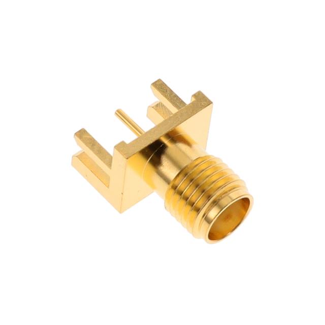
The default signal path is fully passive and does not require power. RF enters through an edge-mount SMA connector, passes through an ESD protection diode, then through a selectable 88–108 MHz FM bandpass filter, and finally exits through another SMA connector to the SDR. The board uses a 50 ohm RF design approach with a 4-layer PCB stackup: top layer for RF routing and components, inner ground planes for return paths and shielding, and ground pours/stitching vias for improved RF layout.
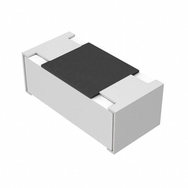
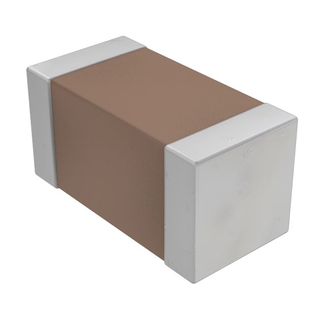
The FM filter is implemented as a 5th-order Chebyshev-style bandpass filter using LC resonator sections. The filter path is selected with 0 ohm resistors, making the board easy to reconfigure without adding software-controlled RF switches. The auxiliary filter bay is left unpopulated by default and is intended for future bands such as ADS-B, AIS, amateur radio, or other SDR experiments.
ClarionRF also includes an optional PSA4-5043+ LNA footprint. This LNA section is marked DNP by default and is bypassed using a populated 0 ohm resistor. This was done intentionally because FM broadcast signals can be strong enough to overload an RTL-SDR if too much gain is added. The passive default mode is safer for first testing, while the optional LNA path allows future experimentation if additional gain is needed.
I decided to make this project because I wanted a portfolio-quality RF PCB that connects directly to a larger SDR/passive radar system. It demonstrates RF schematic design, filter design, 50 ohm PCB layout, modular hardware planning, and practical design tradeoffs such as bypassable gain stages and DNP expansion sections. The board is intended as Rev 1 of a larger passive radar hardware platform.
ClarionRF_V1
*PCBWay community is a sharing platform. We are not responsible for any design issues and parameter issues (board thickness, surface finish, etc.) you choose.


Raspberry Pi 5 7 Inch Touch Screen IPS 1024x600 HD LCD HDMI-compatible Display for RPI 4B 3B+ OPI 5 AIDA64 PC Secondary Screen(Without Speaker)
BUY NOW


- Comments(0)
- Likes(0)
 More by Engineer
-
Programmable Mist Maker - XIAO / QT PY Extension
14 0 0 -
-
Bluetooth Speaker with Custom designed 15W dual channel Audio Amplifier
19 0 0 -
-
-
-
-
ARPS-2 – Arduino-Compatible Robot Project Shield for Arduino UNO
2699 0 5 -
A Compact Charging Breakout Board For Waveshare ESP32-C3
3188 3 8