


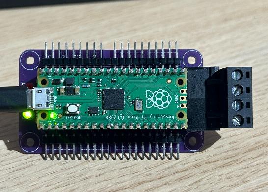
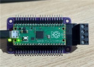
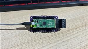
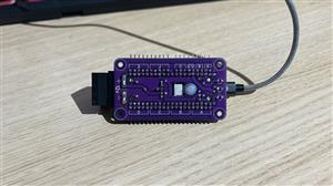


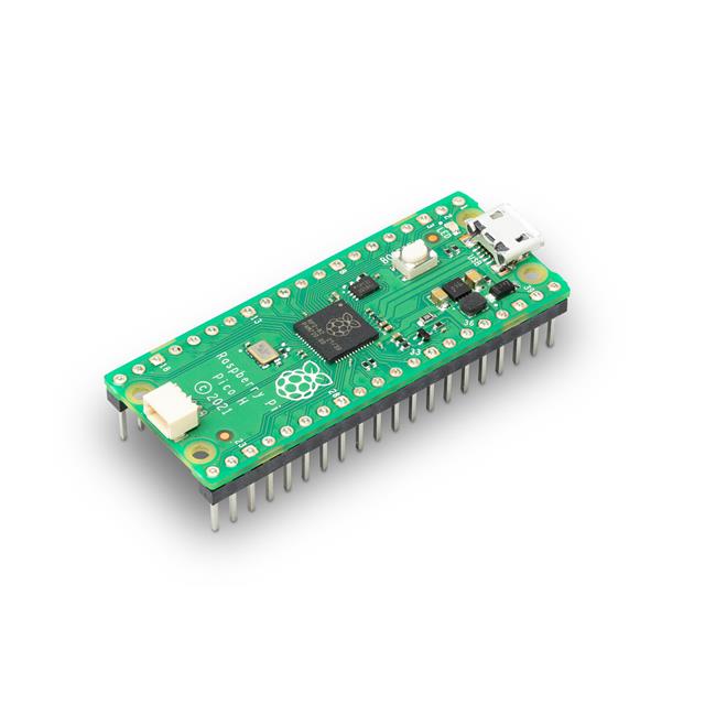
3-Series: Raspberry Pi Pico Carrier
This is a carrier board for breaking out and securely mounting a Raspberry Pi Pico micro-controller. It exposes all 26 GPIO pins in six groups of four (A-F) and one of two (G).
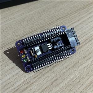
This carrier board can be powered using any combination of three methods:
- USB via the micro-controller's programming port
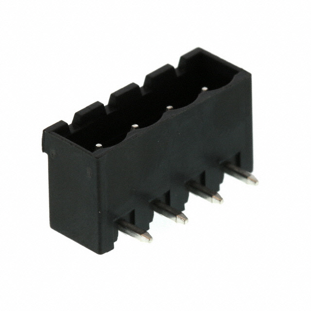
- Externally using the 4-pin power connector (supports passthrough)
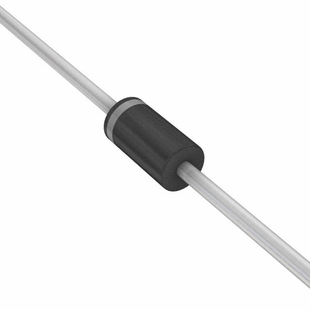
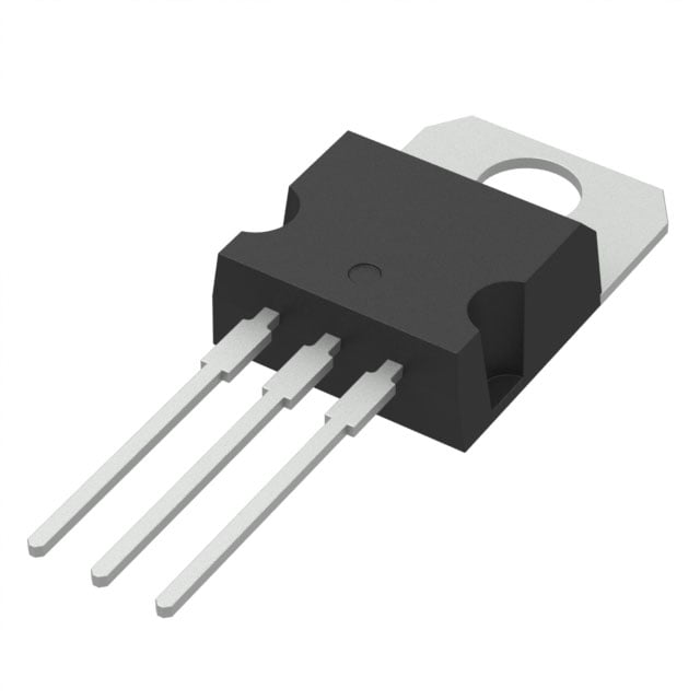
- Via the marked 5v headers (opposite end must have a 1N5819 schottky diode to prevent backfeeding to non-logic circuits)
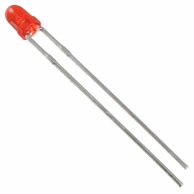
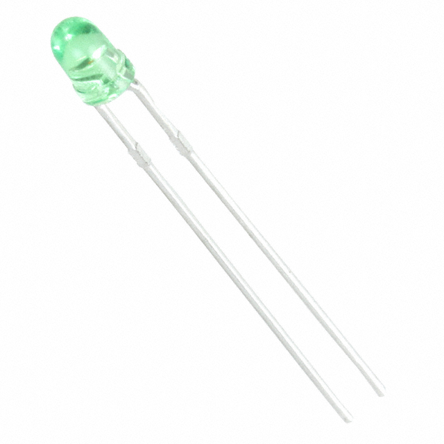
This carrier board also features 3 LEDs to indicate the state of power delivery:
- Green: CPU 3v3 rail
- Yellow: USB power
- Red: external 9-12v power
About the `3-Series`
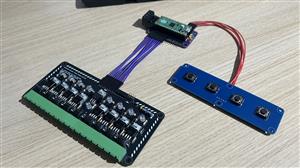
The concept of the 3-Series is centred around an ecosystem of electronics prototyping components that can be mounted easily into projects without having to make estimations on the gaps between mounting posts. All boards within the 3-Series feature M3 mounting holes on a 30mm grid.
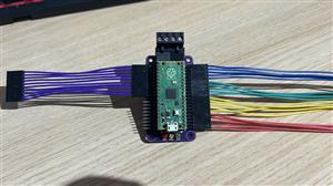
The `PicoPort` Interconnect
Every connection between 3-Series boards is centred around a common 5-pole connection, comprising of one central ground pin flanked by two GPIO pins on both sides. For connections requiring more than four GPIO pins, for example, where 8 outputs is required, two neighbouring ports can be linked together using a 10-pole connection.
This micro-controller breakout board exposes 6 of these groups marked A to F.
Notes
- Bill of materials are only illustrative or generic examples, this project will work so long as pin-for-pin-compatible equivalents are used
- For continuity, this carrier board does not break out out the `3V3_EN` (pin 37) and `RUN` (pin 30) connections, replaced with GND and GPIO26, the absent pin shown in the photos is where GPIO26 would normally be
- `ADC_VREF` is internally-tied to `3V3_OUT` and not broken out
- Port G (GPIO 27/28) does not follow the `PicoPort` spec, but is provided for user convenience and to enable access to all 26 GPIO connections, pin 31 is usually where GPIO 26 would normally be
- Raspberry Pi, the Raspberry Pi logo, are registered trademarks of the Raspberry Pi Foundation and used with permission under BSD 3-Clause license without endorsement
3-Series: Raspberry Pi Pico Carrier
*PCBWay community is a sharing platform. We are not responsible for any design issues and parameter issues (board thickness, surface finish, etc.) you choose.

- ✖ | No sharing or redistributing in any way of the 3D files or derivatives
- ✖ | No remixing
- ✖ | Non-commercial Use (only for personal use)


Raspberry Pi 5 7 Inch Touch Screen IPS 1024x600 HD LCD HDMI-compatible Display for RPI 4B 3B+ OPI 5 AIDA64 PC Secondary Screen(Without Speaker)
BUY NOW


- Comments(3)
- Likes(0)
More by BritKig Animegao
-
Programmable Mist Maker - XIAO / QT PY Extension
419 0 0 -
RadioHAT - Raspberry Pi radio development platform
324 0 1 -
-
-
-
-
ARPS-2 – Arduino-Compatible Robot Project Shield for Arduino UNO
2879 0 6 -
A Compact Charging Breakout Board For Waveshare ESP32-C3
3381 3 8 -
AI-driven LoRa & LLM-enabled Kiosk & Food Delivery System
3699 2 2


