


|
KiCADKicad
|
2026 SAINTCon Mini Badge
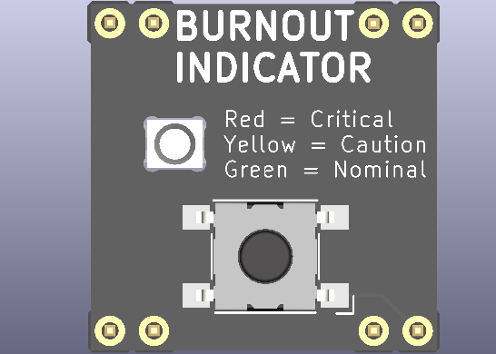
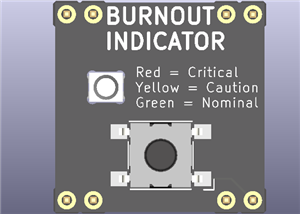
The Burnout Status MiniBadge is a SAINTCON-compatible conference minibadge that allows the wearer to communicate their current burnout level using a single RGB LED and one push button. The concept is intentionally simple, humorous, and instantly recognizable by anyone who has attended a technical conference or worked in the IT and cybersecurity industry.
Technology conferences are exciting, but they are also mentally exhausting. Long days of presentations, late-night events, networking, competitions, and very little sleep eventually catch up with everyone. This badge turns that shared experience into a lighthearted conversation starter.
Using a single button, the wearer can select one of three burnout levels:
- Green – Doing fine.
- Yellow – Running low on energy.
- Red – Officially burned out.
The badge also includes two hidden "easter egg" modes. Holding the button for three seconds activates a flashing SOS distress signal in Morse code, while holding the button for six seconds activates a continuous rainbow animation representing the point where you've accepted the chaos and simply embraced conference life.
The project was designed to be inexpensive, easy to assemble by hand, and simple enough that anyone interested in embedded systems or PCB design can understand how it works.
This is my third conference PCB design and my latest hardware project. Previous conference projects focused on adding more hardware and more features. With this project, I wanted to challenge myself in a different way by intentionally reducing the design to its essentials.
Many conference badges include displays, batteries, radios, sensors, or dozens of LEDs. Those projects are impressive, but they also increase cost, complexity, and assembly time.
The goal of this project was to answer a different question:
"How much personality can a badge have with only one button and one RGB LED?"
The result is a badge that is immediately understandable while remaining inexpensive enough to build in quantity and hand out to friends at SAINTCON.
As an IT instructor and cybersecurity enthusiast, I spend a great deal of time around students, professionals, and conference attendees who all understand burnout. The joke requires almost no explanation, making it a fun icebreaker throughout the conference.
From a technical standpoint, the project also provided an opportunity to design a complete embedded system from start to finish, including:
- Schematic capture
- PCB layout
- Component selection
- Firmware development
- Manufacturing
- Hand assembly
- Hardware
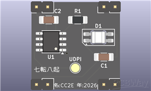
The Burnout Status MiniBadge uses only a handful of components:
- ATtiny402 microcontroller
- SK6812MINI-E reverse-mount addressable RGB LED
- One surface-mount tactile pushbutton
- One 330 Ω resistor
- Two 0.1 µF ceramic decoupling capacitors
The reverse-mount RGB LED is installed on the back of the PCB and shines through a circular opening in the board, allowing the front of the badge to remain clean while hiding all electronic components from view.
Programming is performed through the UPDI interface.
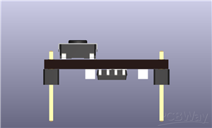
The badge follows the official SAINTCON MiniBadge mechanical specification and connects to a host badge using a standard 8-pin header.
Firmware
The firmware is written for the ATtiny402 using the Arduino IDE and megaTinyCore.
Internally, the badge operates as a simple state machine.
Normal Modes
A short press cycles between:
- Green
- Yellow
- Red
These three colors represent increasing levels of burnout.
SOS Mode
Holding the button for approximately three seconds places the badge into SOS mode.
The LED repeatedly flashes the Morse code distress signal:
... --- ...
This mode continues indefinitely until another valid button action changes the mode.
Rainbow Mode
Holding the button for approximately six seconds activates Rainbow Mode.
The LED continuously cycles through the color spectrum until another button action is performed.
Rainbow Mode can be entered from any other operating mode.
PCB Design
The PCB was designed as a compact two-layer board with all components mounted on the back side.
Design goals included:
- Small component count
- Easy hand assembly
- Low manufacturing cost
- Clean front-side appearance
- Compatibility with the SAINTCON MiniBadge standard
The front of the badge contains only the artwork, button, and LED window. All electronic components are hidden on the reverse side to keep the design visually clean.
The PCB uses:
- Black solder mask
- White silkscreen
- ENIG surface finish
- The reverse-mounted RGB LED provides the only illumination, creating a simple but effective visual indicator.
Design Philosophy
This project intentionally avoids unnecessary complexity.
Instead of trying to include every available feature, the design focuses on creating a memorable user experience using the fewest possible components.
The entire badge consists of:
- One microcontroller
- One RGB LED
- One button
Despite the minimal hardware, the badge provides multiple operating modes, persistent status indication, and a humorous interaction that conference attendees can immediately understand.
Sometimes the simplest projects are the ones people remember most.
Manufacturing
The badge was designed for low-cost manufacturing and straightforward hand assembly.
All components were selected with availability and ease of soldering in mind. The SOIC-8 microcontroller, 1206 passive components, and 6 mm tactile switch allow the entire badge to be assembled using common hobbyist tools.
The goal was to create a project that could be reproduced by students, makers, and first-time PCB designers without requiring specialized equipment.
Possible future revisions include:
- Configurable brightness levels
- Additional conference-themed animation modes
- User-selectable color profiles
- Battery-powered standalone version
- Wireless synchronization between multiple badges
For this initial revision, however, the emphasis was on simplicity, reliability, and delivering a polished conference accessory that reflects a shared experience within the cybersecurity community.
2026 SAINTCon Mini Badge
*PCBWay community is a sharing platform. We are not responsible for any design issues and parameter issues (board thickness, surface finish, etc.) you choose.


Raspberry Pi 5 7 Inch Touch Screen IPS 1024x600 HD LCD HDMI-compatible Display for RPI 4B 3B+ OPI 5 AIDA64 PC Secondary Screen(Without Speaker)
BUY NOW


- Comments(0)
- Likes(0)
 More by J Kuro
-
Programmable Mist Maker - XIAO / QT PY Extension
554 1 0 -
RadioHAT - Raspberry Pi radio development platform
438 0 1 -
-
-
-
-
ARPS-2 – Arduino-Compatible Robot Project Shield for Arduino UNO
2950 0 6 -
A Compact Charging Breakout Board For Waveshare ESP32-C3
3463 3 8 -
AI-driven LoRa & LLM-enabled Kiosk & Food Delivery System
3807 2 2


