The package include:

Note:
- No Sensors are included in the PCB
- You need extension wires to connect the sensors in ports P1, P2 and P3.
The Solar Powered WiFi Weather Station V3.0 is more powerful than previous versions by including some new features. This Weather Station is such compact weather station that consists of several meteorological sensors that measure the following parameters:
1. Internal Temperature (BME280)
2.Humidity (BME280)
3. Barometric Pressure (BME280)
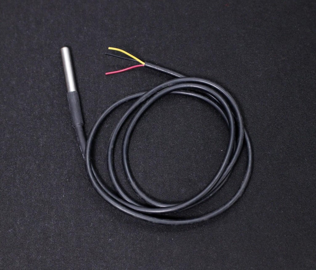
4.External Temperature (DS18B20)
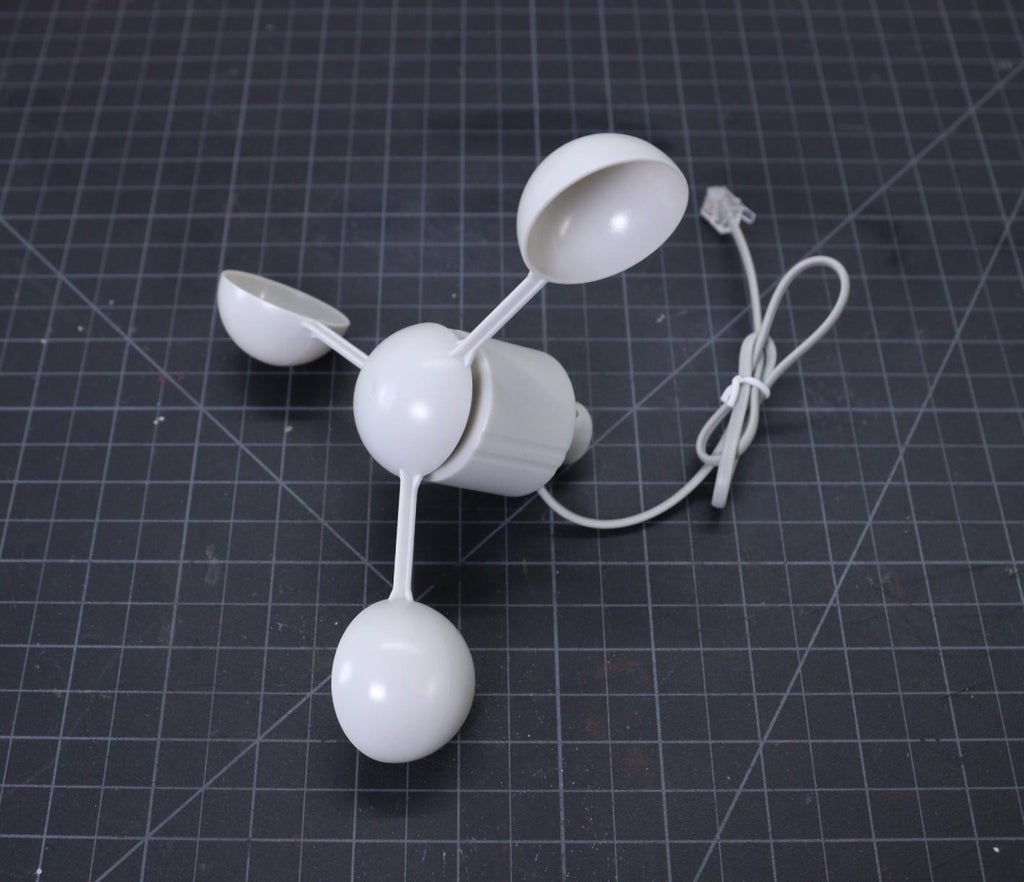
5. Wind Speed ( Sparkfun Weather Meter )
6. Wind Direction ( Sparkfun Weather Meter )
7. Rain Gauge ( Sparkfun Weather Meter )
8. UV Index ( SI1145)
9. Lux Level ( BH1750 )
Why a Weather Station?
Imagine you are residing at a place that is far away from the meteorological department. In such a case, the weather predictions you get may not be the most precise. This is where home weather stations become more advantageous. This small weather station can provide accurate data regarding the weather parameters of where you live.
Today, data on localized weather, known as microclimates, is the new frontier for more precise and accurate weather forecasting. As a result, the collection of weather data is becoming increasingly smaller and gridded.
Applications:
The applications of this type of small portable weather station are vast in the area of smart agriculture, smart city, solar power plants, construction site, etc.
Step 1: Selecting the Power Supply
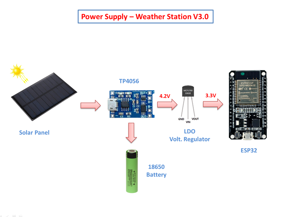
If you are planning to install the weather station at a remote location like your farmhouse, you may not get access to the power grid to run the weather station. To run the station continuously, there must be a continuous power supply otherwise the system will not work. The best way to provide continuous power to the circuit is by using a battery. But in the case of the battery, after some days of run, its juice will run out, and it is a really difficult job to go there and charge it. So a solar charging circuit was proposed to use free energy from the sun to charge the battery and to power the ESP32 board.
Here, I have used a 18650 Li-Ion battery. The battery is charged from a Solar panel through a TP4056 charging module. The TP4056 module comes with a battery protection chip or without the protection chip. I will recommend buying a module that has a battery protection chip included.
The 18650 battery outputs 4.2V when fully charged. The battery voltage is further step down to 3.3V by using a low dropout voltage regulator(MCP1700-3302E).
The output from the voltage regulator will power the ESP32 through the 3.3V pin.
Step 2: Power Supply Circuit
The operating voltage of the ESP32 is 3.3V whereas the fully charged battery voltage is 4.2V. So we have to step down the battery voltage from 4.2V to 3.3V, which can easily be done by a linear voltage regulator but unfortunately, it is not at all recommended for this project. Because all the linear regulators require an input voltage at least some minimum amount higher than the desired output voltage. That minimum amount is called the dropout voltage. Due to this reason when battery voltage drops to around 3.7V, the linear voltage regulator will not able to maintain the voltage required voltage ( 3.3V ).
The solution to the above problem is to use a low-dropout or LDO regulator. A low-dropout or LDO regulator is a DC linear regulator which can regulate the output voltage even when the supply voltage is very close to the output voltage. Here we will use an MCP1700 LDO for efficiently powering the Circuit.
A ceramic capacitor ( 0.1uF) and an electrolytic capacitor (100uF) are connected in parallel to the GND and Vout pin of the LDO ( MCP1700 -3.3V ) to smooth the voltage peaks.
The output of the MCP1700 is connected to the ESP32 3.3V pin through a slide switch.
MCP1700 Data Sheet: Download
Step 3: Wind Vane ( Wind Direction Sensor)

The wind vane indicates the direction that the wind is blowing. It is the most complex of the sensors in the Sparkfun Weather Sensor Kit. It has eight reed switches, each connected to a different resistor. As the wind vane rotates, a magnet closes the reed switches and may close two at a time due to their proximity to each other, allowing up to 16 different positions to be indicated. However, in testing the unit, I never could make the device close two switches at once, so although it might be possible theoretically to measure 16 directions, I only get eight. The software takes 16 directions into account, just in case.
An external resistor can be used to form a voltage divider, producing a voltage output that can be measured with an analog to digital converter, on your the microcontroller allows you to determine the direction of the wind vane pointer.
To measure voltage output, I have used a 10kohm external resistor to form a voltage divider with the wind vane resistor ( Rvane). The 10K resistor is connected to 3.3V as shown in the above figure. Then, I connect the middle of the divider to the ESP32 ADC pin (GPIO 35), measure the voltage, and by referring to the table shown above, convert to the wind direction.
The reed switches and resistors arrangement are shown in the above picture. Resistance values for all 16 possible positions are given in the table.
When the wind vane pointer falls in between two switches, the resistance value is considered as the equivalent resistance between the two adjacent resistances. In this situation, the vane’s magnet activates two switches simultaneously, as result they are connected in parallel.
Step 4: Anemometer ( Wind Speed Sensor)

The wind speed sensor is a cup-type anemometer measure wind speed by closing a contact as a magnet moves past a reed switch. As per the datasheet, a wind speed of 2.4km/h (1.4912 mph) causes the switch to close once per second. The anemometer switch is connected to the inner two conductors of the RJ 11 cable shared by the anemometer and wind vane (pins 2 and 3).
The Anemometer is connected to the ESP32 GPIO pin 14 and GND. After that, all we need to do then is to monitor for button presses which is pretty straightforward. We can use the pin interrupts method to monitor the button press ( tips). When the reed switch closes the circuit (pressing the button), it triggers a software event.
If you want to make your own wind sensor, then read this nice Instructable
These are few more 3D printed Wind Sensors:
1. Anemometer
Step 5: Rain Gauge ( Rain Fall Sensor )

Here I have used a most common type of Rain Sensor which is called a Tipping Bucket rain gauge. Basically, there's a little see-saw shape tipper bucket inside the sensor ( see the above picture ). The rain fills up a bucket on one end and it tips over so that it empties and the bucket on the other side starts to fill. Each time the bucket tips it passes a magnet over a reed switch making a momentary electrical connection. The buckets are calibrated to a volume of water, which means if we can count how many times the switch closes we can calculate how much rainfall there's been.
Much like the wind speed gauge, the rainfall gauge generates ticks to tally the amount of rain that has fallen. Count ticks to determine how much rain has fallen recently. Each tick represents 0.011" ( 0.28mm ) of rainfall. This sensor is connected to pin 25 of the ESP32.
The rain gauge that I have used here is from Sparkfun. It has an RJ-11 plug on the end, you can directly plug it into the Weather Station V3.0 PCB.
You can make your 3D printed Rain Gauge by following this article
Step 6: Measuring the Rainfall
In the previous step, we have discussed that each time the bucket tips, it passes a magnet over a reed switch making a momentary electrical connection. Here each tip of the bucket in the rain gauge can be assumed as a button press. We can easily then connect the gauge as if it were a button.
The rain gauge is connected to the ESP GPIO pin 25 and GND. After that, all we need to do then is to monitor for button presses which is pretty straight forward. We can use the pin interrupts method to monitor the button press ( tips). When the reed switch closes the circuit (pressing the button, the bucket tipping), it triggers a software event.
Here I am using attachInterrupt()to monitor the number of tips. You can find the details from Arduino Page.
Step 7: Monitoring Pressure ,Temperature and Humidity by BME280

In the earlier days, weather parameters like ambient temperature, humidity, and barometric pressure were measured with separate analog instruments: thermometer, hygrometer, and barometer. But today the market is flooded with cheap and efficient digital sensors that can be used to measure a variety of environmental parameters. The best examples are sensors like DHT11, DHT 22, BMP180, BMP/E280, etc.
In this project, we will use BMP280 / BME280 sensor.
BMP280: BMP280 is a sophisticated sensor that very accurately measures barometric pressure and temperature with reasonable accuracy. The BME280 is the next-generation of sensors from Bosch and is the upgrade to the BMP085/BMP180/BMP183 - with a low altitude noise of 0.25m and the same fast conversion time. The advantage of this sensor is that it can use either I2C or SPI for communication with the microcontroller. For simple easy wiring, I will suggest buying the I2C version board.
BME280: The new BME280 sensor, an environmental sensor with temperature, barometric pressure, and humidity. The BME280 is the next-generation of sensors from Bosch and is the upgrade to the BMP280. This precision sensor from Bosch is the best low-cost sensing solution for measuring humidity with ±3% accuracy, barometric pressure with ±1 hPa absolute accuracy, and temperature with ±1.0°C accuracy. It can be used in both I2C and SPI.
Note:BME280 can measure humidity but BMP280 can't. In the market, BMP280 is also available by the name of BME280. So be sure whether it is a BMP280 or BME280.
Step 8: Monitoring UV Index - SI1145 Sensor

The Si1145 is a sensor with a calibrated UV sensing element that can calculate the UV Index. It can communicate via I2C communication (address 0x60). You can hook up this sensor with I2C port in the PCB which is located at the bottom left of the ESP board.
The SI1145 sensor really doesn’t have an actual UV sensor! Instead, it looks at the amount of visible and IR light it receives from the Sun and uses a formula to calculate the UV index, right down to two decimal points.
You can read this article to know more about the UV sensor.
If you need a more accurate measurement of UV Index, you may use the VEML6070 sensor. Unlike the Si1145, this sensor will not give you UV Index readings. However, the Si1145 does UV Index approximations based on light level, not true UV sensing. The VEML6070 in contrast does have a real light sensor in the UV spectrum.
You can read this tutorial for writing the code and using its library.
Step 9: Monitoring Lux Level - BH1750 Sensor

The BH1750 Ambient Light Sensor Module is based on the digital Ambient Light Sensor IC BH1750FVI developed by ROHM Semiconductor. It is a digital IC with built-in 16-bit illuminance to digital converter.
The output of this sensor is in LUX (lx), so it does not require any further calculations. Lux is the unit to measure Light intensity. It measures the intensity according to the amount of light hitting on a particular area. One lux is equal to one lumen per square meter.
For communication with external devices like ESP32, the BH1750 Ambient Light Sensor IC uses I2C Bus Interface.
Pin Description
VCC – 3.3V to 3.3V
GND – VCC
SCL – SCL
SDA – SCL
ADD – I2C Device Address ( Kept Open )
You can read this instructable for information on BH1750 light sensor
Step 10: External Temperature Sensor

If you need, you can connect an external temperature sensor like DS18B20 to monitor the ambient temperature. DS18B20 is One Wire interface Temperature sensor manufactured by Dallas Semiconductor Corp. It requires only one digital pin for two-way communication with a microcontroller. I have hooked up this sensor with ESP32 GPIO pin4.
The DS18B20 comes usually in two form factors. One that comes in the TO-92 package looks exactly like an ordinary transistor and another one in a waterproof probe with an extension cable. I have used DS18B20 probe for measuring the temperature. It uses a one-wire protocol to communicate with the ESP32. It can be hooked up to the 3 pin screw terminal on the PCB.
To interface with the DS18B20 temperature sensor, you need to install the One Wire library and the Dallas Temperature library. You can read this article for more details on the DS18B20 sensor.
Step 11: Monitoring Battery Voltage

The weather station is run by a 18650 Li-Ion battery, so it is essential to monitor the battery status. The max voltage input to the ESP32 board is around 3.2~3.3V but a fully charged 18650 battery voltage is 4.2V. So to measure this voltage we have to step down the voltage by using a voltage divider network.
The voltage divider is made up of 27k (R1) and 100k (R2).
When you have your ESP32 powered with batteries or solar-powered as in this case, it can be very useful to monitor the battery level. One way to do that is to read the output voltage of the battery using an analog pin of the ESP32.
However, the battery we’re using here outputs a maximum of 4.2V when fully charged, but the ESP32 GPIOs work at 3.3V. So, we need to add a voltage divider so that we’re able to read the voltage from the battery.
The voltage divider formula is as follows:
Vout = (Vbat*R2)/(R1+R2)
So, if we use R1=27k Ohm, and R2=100k Ohm,
We get: 1 Vout = (4.2*100k)/(27k + 100k) = 3.307V
So, when the battery is fully charged, the Vout outputs 3.307V that we can read with an ESP32 GPIO pin. To select the voltage divider resistance values, you can use this online calculator.
Step 12: ESP32 - Thingspeak-Deep-Sleep
The heart of our Weather Station is an ESP8266 SOC which is a power-hungry chip. When your project is powered by a plug-in the wall, you tend not to care too much about power consumption. But if you are going to power your project with batteries, every mA counts.
Our objective is to run the device by using a 18650 Li-Ion battery. To run the ESP32 by using a battery, we have to lower the power consumption. To do that, we’ll use the Deep Sleep Mode which is the most power-efficient option for the ESP chip. It allows to put the ESP32 into hibernation and saves the battery. You can wake up the ESP at regular intervals to make measurements and publish them.
Calculating Battery Life:
The ESP32 consumes around 75mA in normal operation and hits about 150mA while transmitting data over WiFi. and in Deep Sleep about 10uA. The ESP32 takes ~ 30secs to upload data.
Battery Life calculations:
Battery Used: 3400mAh / 3.7V 18650 Li-Ion
Publish Interval = 10mins ( ON Time: 30 sec and Sleep Time: 9 mins 30 sec )
Total number of Readings / Hour = 60/10 = 6
Power consumption per hour (ON time) = 6 x 150 mA * 30 / 3600 = 7.5mA
Sleep time = 6 x 10uA * 570 / 3600 = 0.0095 mA
Total time in hours on battery = 3400 / (7.5+0.0095) = 452.76Hrs
Total days on battery = 452.76/24 = 18.86 Days
Step 13: Solar Panel Selection

The amount of solar insolation varies according to which part of the globe you are located at. To find out the amount of solar insolation in your area, you can use the Global Solar Atlas. By taking consideration into a minimum of 1 hour of full sunlight, we are going to select the solar panel.
From the previous step, it is concluded that the average current consumption is 7.5 mA
Charge required for running the device for the whole day = 7.5 mA x 24 Hours = 180 mAh
So, our target is to generate 180 mAh in 1 hour.
To charge a 3.7V Li-Ion battery, a solar panel of voltage 5 to 6V is adequate.
Required Solar Panel rating = 180 mA at a voltage of around 5 to 6 volts.
Solar panel rating = 180 mA x 5V = 0.9 Watt, by considering some losses, I have selected a higher rating solar panel.
Solar Panel Selected: used a 5V,250mA Solar Panel ( 110 x 69 mm)
Step 14: Already Assembled on PCBWay

Step 15: 3D Printed Enclosure

The ideal enclosure for keeping the weather sensors is the Stevenson Screen. A Stevenson screen is an enclosure to shield meteorological sensors against precipitation and direct heat radiation from outside sources, while still allowing air to circulate freely around them.
My friend Glen from New Zealand helped me to make this professional-grade Stevenson Screen. I really appreciate his help in making this project successful.
This has a simple wall mount and a 2 part cover to isolate the heat transfer from the solar panel. The V3.0 design has a provision for mounting a UV Index sensor on the top. Apart from this, the top cover for mounting solar panel is kept away from the main enclosure to avoid heat transfer from the solar panel to the interior part of the enclosure.
The Stevenson Screen has 6 parts:
1. PCB Mount Frame
2. Bottom Plate
3. Bottom Mount
4. Middle Rings x 12 Nos
5. Screen Top Cover
6.Top Cover for Solar Panel Mount ( Solar Panel Size: 110 x 69 mm )
7. M6 Rod x 4 Nos
I used my Creality 3D printer and 1.75 mm white PLA filament to print the parts. I will recommend using ABS or PTEG filament instead of using PLA.
You can refer to the above explosion diagram to assemble the 3D printed parts.
You can download the .STL files from Thingiverse
You can download the STEP files from GRABCAD for any modification.
Step 16: Assemble the 3D Printed Parts


2 More Images
The assembly process is clearly indicated in the explosion diagram shown above. It is broadly as below:
1. Stacking 12 numbers of middle rings one above the others
2. Mounting the PCB
3. Mounting Solar Panel and UV Sensor on Top Cover
4. Joining the Bottom plate, Middle ring, and Top Cover
Step 17: Assemble the Middle Rings

The assembling process is very simple, just stack one above the others. After stacking all the middle rings, insert the 4 x M6 rods at the corners. The M6 rods can be a metal one or 3D printed one, here I have used the 3D printed rods.
If you are using 3D printed rods, then I will suggest inserting the M3 rods at the early stage, i.e. after stacking 2 or 3 rings is perfect. Then insert the remaining middle rings one by one. I have broken 2 rods during the assembling because I did one mistake that stacked all the rings first and then tried to push the rods at the corner holes.
Step 18: Mount the PCB

The PCB Mount Frame is designed to mount the V3.0 PCB ( 100 x 86 mm). The PCB mount has text on it to show orientation and the battery goes to the top of the assembly.
Align the PCB in such a way that the battery holder on the PCB and the mounting plate match each other. Once it is matched the other sides will automatically be matched. Now you have to align the PCB holes with the PCB mounting holes ( looks like 4 standoffs ). Then secure the PCB with 4xM3 Nuts.
After installing the PCB, slide the PCB mount into the middle ring assembly as shown in the above picture.
Step 19: Connect the Wind and Rain Sensors

First, insert the two cables from the wind and rain sensor through the round hole in the Bottom Mount. Connect the two cables to RJ11 connectors ( wind and rain sensor) on the PCB. The connector are labeled as " Wind Sensor " and " Rain Sensor ".
Install the bottom plate and secure it with 4 M3 nuts as shown in the above picture.
Now you can install the bottom mount into the bottom plate and then secure it with a locking nut ( M4).
Note: For a neat and cleaner look, keep the sensor cables toward the bottom mount ( backside ).
Step 20: Mount the Solar Panel

The Solar panel slot in the top cover is designed to hold a 110 x 69 mm solar panel. Here, I have used a 1.25W solar panel.
Apply a small amount of flux to the soldering pads on the solar panel. Then, solder a 22 AWG red wire to the positive terminal and a black wire to the negative terminal of the Solar Panel.
Insert the two wires into the holes in the top cover as shown above. Use silicon glue to fix the Solar Panel and press it some time for proper bonding. Seal the holes from the inside by using a waterproof sealant or silicone glue. I will recommend not to use hot glue, I have used it in my earlier version, it got melt when exposed to bright sunlight during the hot summer.
Here I have used T-8000 glue for mounting the solar panel as well as sealing the cable holes. It is a transparent glue, so it's hardly visible where the glue is used. The main problem with this glue is that it takes a lot of time to dry out.
Step 21: Mount the UV Sensor

The UV sensor module is comprised of UV sensors along with other electronic components to work it properly. Only the sensor part is responsible for sensing the UV light, so it should be exposed to the light.
The top cover is designed to hold the UV Sensor module ( GY1145 ) on a peg and a small clearance is given in the slot for the soldering pins on the module.
First, cover the UV sensor ( marked in the yellow border - see the image ) by using masking tape, then mount it on the top cover. You may need small alignment to expose the sensor through the square hole on the enclosure.
Now apply some silicone sealant to stop any water from entering through the opening. After drying the sealant, remove the masking tape by using tweezers. After removal of the tape you will reveal a clean sensor surface
Note: No window is provided over the UV sensor because it will give a wrong reading.
Step 22: Connect the Solar Panel and UV Sensor

Solder 4 jumper wires to the module pins ( VIN, GND, SDA, and SCL).
There are 3 holes in the top cover, 2 central ones for where the solar panel wires are soldered onto the panel and there is a single hole at the front, this is for the wire from the UV sensor board.
Assemble these wires in place using silicone to seal up the holes.
Now connect the solar panel red wire to the positive and black wire to the negative terminal of the Solar In screw terminal on the PCB.
Then connect the wires coming from the UV sensor to the UV sensor header ( P2 ) on the PCB.
Step 23: Software and Libraries
To use the ESP32 board with the Arduino library, you'll have to use the Arduino IDE with ESP32 board support. If you haven't already done that yet, you can easily install ESP32 Board support to your Arduino IDE by following this tutorial by Sparkfun.
Install Libraries:
Before uploading the code install the following libraries :
1. ESP32
2. Blynk
3. BME280
4. Adafruit_SI1145_Library
5. BH1750
6. One Wire
7. Dallas Temperature
How to Install the Libraries?
You can read this tutorial by Sparkfun to install the Arduino libraries.
In my earlier version, there are two separate codes for Blynk and Thinspeak but in this version, we have written a single piece of code. The user has to only comment out a single line of code for Blynk or Thingspeak.
Step 24: Uploading Sensor Data to ThingSpeak

First, create an account on ThingSpeak.
Then create a new Channel on your ThingSpeak account.
Find How to Create a New Channel Fill Field 1 as Temperature, Field 2 as Humidity, Field 3 Pressure, Field 4 as UV Index, Field 5 as Wind Speed, Field 6 as Wind Direction, Field 7 as Rain Fall, and Field 8 as Battery Voltage
In your ThingSpeak account select “Channel” and then “My Channel”.
Click on your channel name.
Click on “API Keys” tab and copy the “Write API Key”
Open the Solar_Weather_Station_ThingSpeak code.
Replace the “WRITE API ”with the copied “Write API Key”.
You can see my live feed
Step 25: Interfacing With Blynk App
Blynk is the most popular Internet of Things platform for connecting any hardware to the cloud, designing apps to control them, and managing your deployed products at scale. With Blynk Library you can connect over 400 hardware models including ESP8266, ESP32, NodeMCU & Arduino to the Blynk Cloud.
Step-1: Download the Blynk app
1. For Android
2. For iPhone
Step-2: Get the Auth Token
In order to connect the Blynk App and your hardware, you need an Auth Token.
1. Create a new account in the Blynk App.
2. Press the QR icon on the top menu bar. Create a clone of this Project by scanning the QR code shown above. Once it detected successfully, the whole project will be on your phone immediately.
I've made the Sol Weather Station app. You are welcome to try it out!
To start using it:
1. Download Blynk App: http://j.mp/blynk_Android or http://j.mp/blynk_Android
2. Touch the QR-code icon and point the camera to the code below 3. Enjoy my app!
3. After the project was created, we will send you Auth Token over email.
4. Check your email inbox and find the Auth Token.
Step-3: Preparing Arduino IDE for Wemos Board
To upload the Arduino code to Wemos board, you have to follow this Instructables
Step-4: Arduino Sketch
After installing the above libraries, paste the Arduino code given below. Enter the auth code from step-1,ssid, and password of your router. Then upload the code.
Step 26: Weather Station Installation

Once you have confirmed that your weather station PCB along with all the sensors, working perfectly, you need to design and make a mount for it. I have used a wooden pole ( 4cm x 8cm x 300 cm ) to mount the sensors and the 3D-printed Stevenson Screen.
If you purchase the entire Weather Meters Kit, then you don't have to worry about mounting the wind and rain sensor. But if you purchase the independent sensor, you may need some mounting arrangement. I found a nice wind sensor holder from Thingiverse.
First I mount the wind sensors ( Wind Vane and Anemometer ) by using the 3D printed wall mounts. I have installed the wind vane and anemometers by using cable ties. After that, mounted them on the wooden pole by using two screws. You can see the above picture for better understanding.
Similarly, I have mounted the rain sensor on the wooden pole. But the holder used for it is a ready-made one. In the future, I will make a 3D printed holder for it so you don't have to buy it.
At last, mount the external temperature sensor ( DS18B20 ) on the pole by using cable ties. After installing all the sensors, you have to route all the cables from the sensors to the Stevenson Screen.
Note: Always use good quality cable ties which is specially made for outdoor use ( UV-resistant ).
Now it is time to install the Stevenson Screen which we have made earlier. Install the Bottom Mount on the wooden pole by using 4 screws.
Suitable Location for Installation:
The location of your weather station is the most important part of the installation. If your weather station is located under a tree or an overhang, the rainfall data measured by the station will not be correct. If you place your weather station in an alley, you could very well get a wind tunnel effect on the anemometer, resulting in erroneous wind data. If you want to measure sunlight you cannot have the sensor in a shadow. So make sure that there is sufficient clearance around and above the weather station.
You can read this nice article on Weather Station Installation.
Step 27: Conclusion and Future Goal

It took me a lot of time to make the circuit, making the PCB prototype, rectifying the errors in the PCB prototype, testing the PCB, making the enclosure, and then assembling and installing them. So I had not enough time left to concentrate on the software part. I am entering this project in Microcontroller Contest, the deadline is 29.03.2021. So I have no options to wait and complete the full software. The software attached here is a basic building block of the project, I will update it regularly with new features.
My future goals are :
1. Software for Implementing ESPHome and Home Assistant
2. Software for implementing MQTT
3. Optimizing the Power Consumption
4. Implementing LORA communication ( Probably in V4.0 )
Thanks for reading my Instructable. If you like my project, don't forget to share it.
Comments and feedback are always welcome.
https://thingspeak.com/channels/1032528