Summary: Using off the shelf hardware to measure vibration and transmit using LoRa.
Here we are again. I’ve been working on a little clandestine project, I can’t fully name. Who is it for? The real application? What I can talk about is the tech.
It’s a sensor project over a wireless protocol. Pretty standard for me. The short version: environment readings and vibration measurement using Meshtastic and LoRa. Completely enclosed local environment with web sockets, no cloud involvement at all. Before we get into the firmware wars, Let me tell you about what hardware I am using.
The base platform
I built the node around RAK Wireless WisBlock gear (ordered through Rokland):
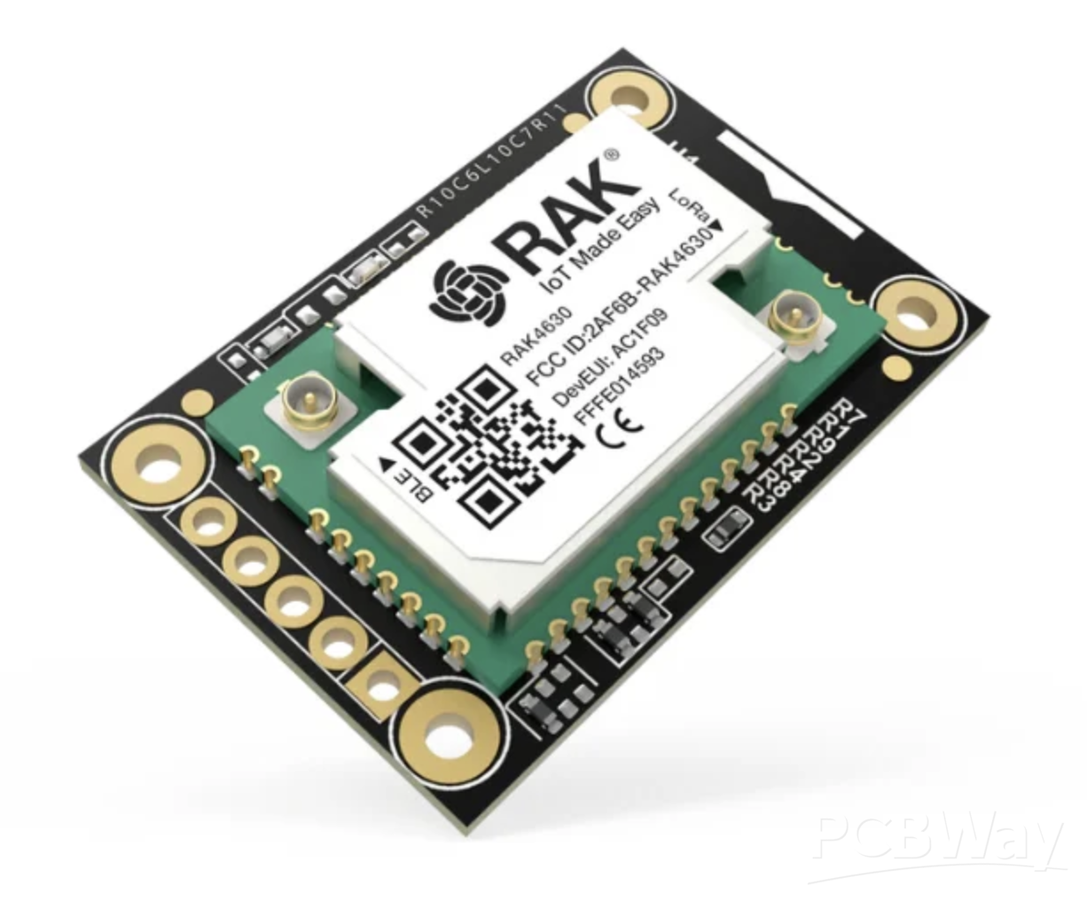
RAK4631 — Nordic nRF52840 BLE core + LoRa SX1262
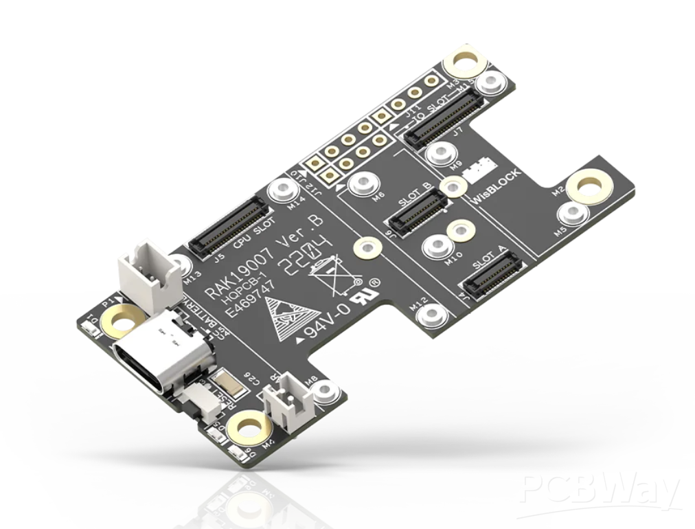
RAK19007 — WisBlock Base Board 2nd Gen
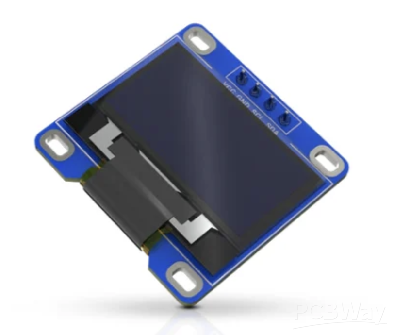
RAK1921 — WisBlock OLED display
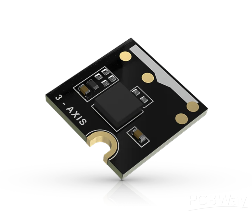
RAK1904 — 3-axis acceleration sensor
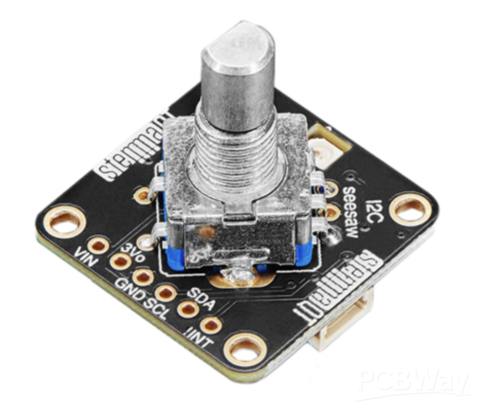
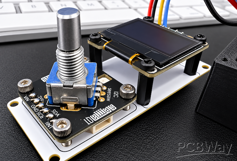
For sensitivity tuning I needed an I²C rotary encoder. Adafruit’s STEMMA QT Rotary Encoder Breakout was one of the few low-cost I²C options that did exactly what I needed. Solid docs, worked flawlessly. A word of caution here, RAKWireless sells an I2C rotary encoder as well, but it is not compatible with the 3-axis sensor. I could get either one to work, but not both. I believe they must share an interrupt, that is my theory. I tried moving the 3-axis sensor to another slot, same problem. So, I went with the Adafruit rotary encoder instead. It has an added bonus of having a Neopixel mounted on the board which comes in handy later.
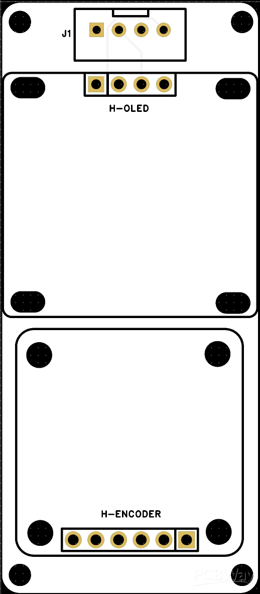
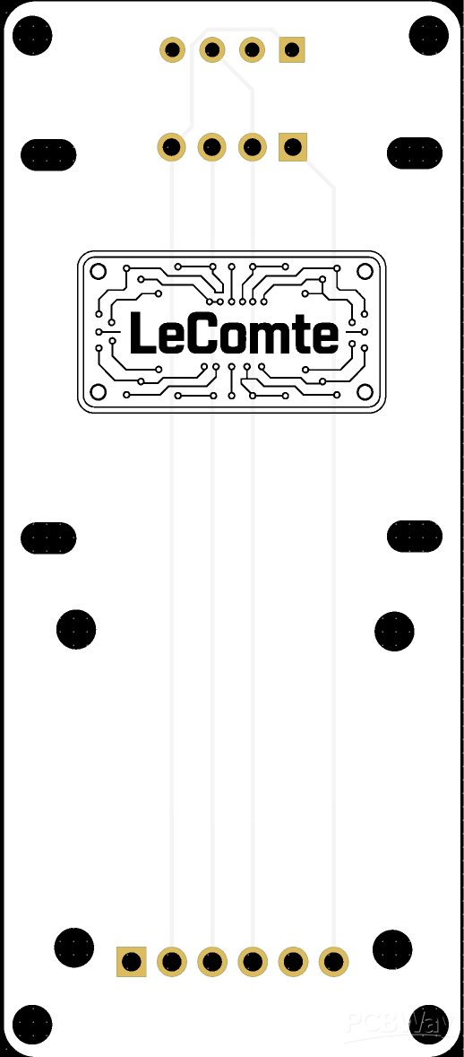
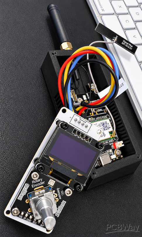
Since the rotary encoder and OLED both use the I2C bus, I designed a small PCB to mount both and attach to the main board with JST connectors. (I hate JST connectors so much, I ended up just soldering wires from the boards because I just struggle with crimping the pins. Maybe someone smarter than this dumb hillbilly, with more patience, can tell me what I am doing wrong) Anyhoo.. Here is the board I designed to hold the OLED and the rotary encoder.
The software (and the headaches)
Architecture-wise, the node collects temperature, humidity, pressure, air quality, and vibration, then sends that data using Meshtastic over LoRa to a LoRa-to-Ethernet gateway that I built. Maybe another blog post on that one soon. The LoRa to Ethernet gateway forwards packets to a websocket on a NodeRed server. Sensor nodes stay mesh-connected so delivery stays reliable. Everything lives in one closed environment — nodes, collection, retention. Nothing over the internet. No cloud. 100% local and encrypted.
Meshtastic’s built-in encryption is a nice bonus. Less time spent worrying about who might be listening in and really easy to configure.
The problem
Meshtastic is great but, there are limitations and they make perfect sense. The biggest one is bandwidth.
LoRa means each node only gets to send a little data at a time. That’s fine for periodic temperature updates or a simple state change. Not so fine for data streaming. Everyone shares the airwaves. One chatty node can drown out the rest.
For temp, humidity, pressure, and air quality, that’s easy, dial the transmit interval so everybody gets a turn. The standard environmental transmission interval is 15-30 minutes in the stock firmware. I changed that interval to 2 minutes in the firmware. This is a closed system; I only care what my nodes are saying. A note of caution though, if you make all the nodes talk a lot, you limit the number of nodes you can have on the mesh, in theory.
Vibration is different. How do you capture vibration from multiple sources, get it across the mesh, and store it without chewing through all the bandwidth?
The iterations
I went through several versions. Some worked. Some taught me things the hard way.
Attempt 1: The firehose. Stream live vibration data. One sensor was fine. Two sent too much data and consumed all the bandwidth, overloading the gateway. It listens for packets, then forwarded them serially to the web socket. I needed a faucet, not a firehose. Lesson one: don’t pour a lake through a straw.
Attempt 2: Duty-cycled sampling. Stream for a few seconds, rest, stream, rest. Fine if you care about long-term trends. I wanted short-term anomalies too — What if i wanted to know if a truck was rolling past the house, or the dogs going full gladiator with a toy. Lesson two: selective data, not just less data.
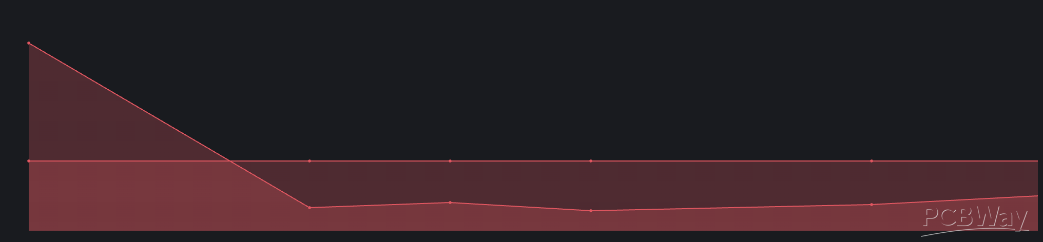
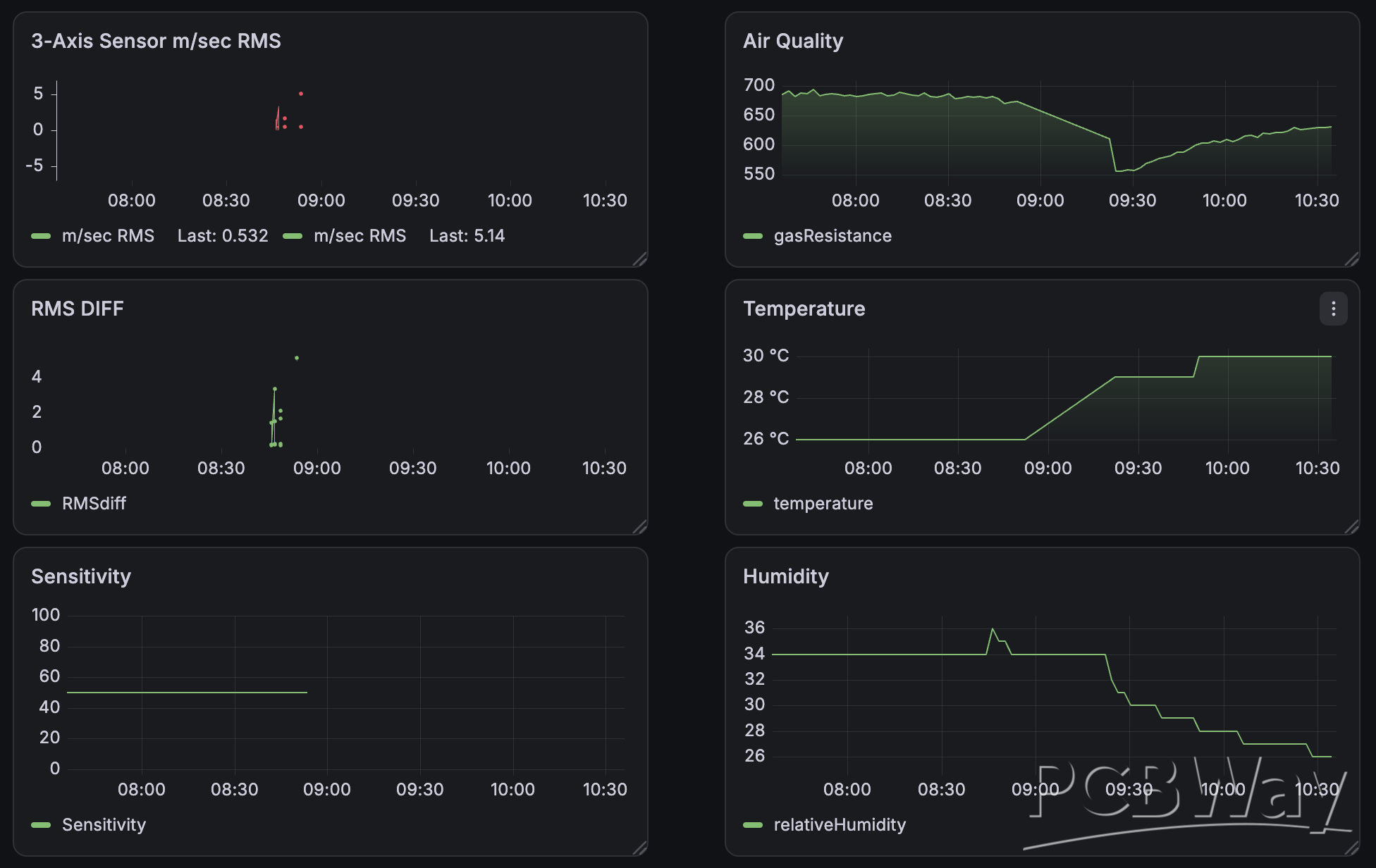
Attempt 3: Baseline + sensitivity. If the thing is already vibrating, what counts as an anomaly? You need a baseline. I set the firmware to wait 30 seconds after boot (so power-on bumps don’t poison the sample), then it collects ambient vibration for 30 seconds and builds a baseline. I used that baseline to compare any readings, used the rotary encoder to set sensitivity (how much above or below baseline is an actual anomaly?) and send 5 packets per anomaly with a 1ms wait between the packets. Below you can see the initial “bump”, then it goes back to almost normal for the remaining 4 packets. This should tell me if there are any resonant frequencies caused by the vibration over time. We will see though. More testing is needed here.
The RAK1904 is a 3-axis accelerometer measuring force in G’s. Range and sample rate both matter when sampling. The sensor has several settings for how it measures force. After the usual loop of fail → fail → finally works, I landed on a 2g range setting (about 4 mg to trigger) and a high sample rate so quick spikes don’t get missed. (See my resonant frequency statement above) Slight variations still showed up in the baseline. At this point I was just reading X, Y, Z G-force though.
I summed the three axes (X+Y+Z) and converted to an RMS-style reading (using 2 mm/s2), which gave me a baseline RMS with a peak. I also added a function where a single out of range sample doesn’t fire on a reading over peak, it wants two consecutive events which is more real world. A vibration doesn’t happen in one direction, see Newtons law. This sampling method is used so a random blip doesn’t spam the mesh. I could see this happening if the power was not clean so, wanted to assure that only real movement generated triggers.
The firmware sends five consecutive readings using custom protobufs inside Meshtastic. I found that there are a bunch of unused protobufs set aside for “custom” work like this. So, I set the protobuf to 255. That way I can filter the data coming into the web socket (after decryption) by what protobuf it was using and that would tell me what was vibration data. Easy filtering into a NodeRed flow..
The rotary encoder adjusts sensitivity between about 0.5 and 15 mm/s², and the OLED shows the sensitivity setting you’re using/changing to.
I setup the Neopixel to flash red on boot, until the baseline is complete. Once complete, the Neopixel changes to a solid green (armed, ready and sensing). When it is triggered, the Neopixel changes to a flashing blue. After it sends the data and the cooldown period, it changes back to green (armed)
I have some real world testing to do, but I believe the sensor ready to be deployed. I am capturing data currently sending it to a local database and using Grafana to review the data.
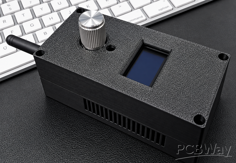
Here are some images of everything put together in a custom 3D printed enclosure. I used Fusion to design the enclosure and 3D printed in PLA for the prototype.
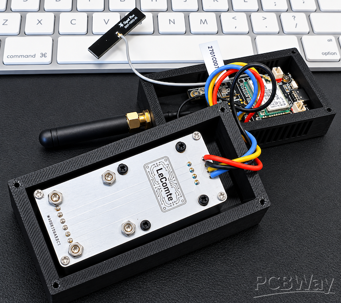
If you want the firmware and related bits, they’re on GitHub: https://github.com/scottlecomte/rak-vibration-sensor
Happy Making Makers!



