By Hesam Moshiri, Anson Bao
An FM transmitter is one of the most popular devices between electronic hobbyist, professionals and even non-technical people. In this article, we gonna learn to how to build an easy, stable and digitally controllable FM transmitter.
For this design, I have selected the VMR6512 module which truly is like a full RF block on a chip!. It eliminates all essential circuitry for a basic FM transmitter such as inductors and trimmers. According to the VMR6512 datasheet: “VMR6512 is a highly integrated FM audio signal transmitter module. It integrates advanced digital signal processor (DSP), frequency synthesizer、RF power amplifier and matching network. So it can realize FM audio modulation without any external components. VMR6512 can also achieve broadcast quality sound by using digital pre-emphasis, digital filtering, automatic gain control, and digital frequency control technologies.“
The operation frequency range is between 88.0MHz to 108.0MHz. the figure-1 shows the schematic diagram of the transmitter.

Figure-1
The schematic diagram of the FM transmitter
The LED D1 shows a proper power supply connection to the circuit(3.3V). The capacitors C1 and C2 reduce the supply noise (0805 packages). Three tactile switches (push button) have been used in the design. The SW1 resets the module, SW3 increases the frequency (+0.1MHz) and SW2 is used to decrease the frequency (-0.1MHz).
The figure-2 shows a view of the top layer and figure-3 shows a view of the bottom layer of the PCB board. The figure-4 shows a 3D view of the assembled board.

Figure-2
A view of the PCB’s top layer
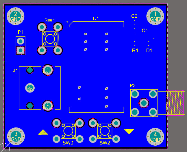
Figure-3
A view of the PCB’s bottom layer

Figure-4
A 3D view of the assembled board
I used an SMA connector for the P2 (Antenna connection). Therefore you can either use it to connect an antenna or use it to connect the output to an RF amplifier. Before increasing the power of your transmitter, check the regulation and broadcasting rules of your country of residence.
You can download the Gerbers or order the PCB here


