label: PCB Material,printed circuit board
Our first PCB post discussed the issues of using FR4 material, concluding with the hopes of using Rogers material for its low loss properties. This week, well take a look at our newest test jig that was fabricated using Rogers material. For 10GBASE-T physical layer testing (IEEE 802.3 Clause 55), we created a test jig that converts a CAT6A Ethernet jack to SMA connectors (named the OctoBoard). The board is made of Rogers RO4350B material which is more expensive than FR4, but is much less lossy. This is critical when testing high speed technologies like 10GBASE-T. Designing a board using Rogers material was a tedious task as many different constraints had to be accounted for such as the dielectric constant (3.66 vs. FR4s 4.5), inner/outer layer thickness, the laminate core thickness, and the bonding ply thickness which all differ from FR4. All of these parameters yielded a trace thickness twice that of a FR4 design for 50 ohm impedance.
We use side launch SMA connectors that use a pad width of 20 mils for the conductor, which matches the 20 mil trace width from our previous FR4 designs. Since the trace width for Rogers design is ~40 mils we had to taper the trace width from the SMA pads. As we dont have a software package to simulate the effects of changing the trace width, we created a prototype board using Rogers material. The prototype board has different trace tapering designs and we measured the insertion loss of each trace design to find the optimal taper method to be used on the OctoBoard.

10GBASE-T Octoboard
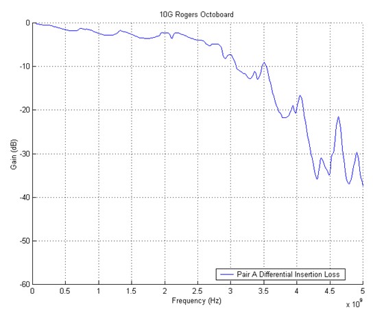
We were pleased to find that the differential insertion loss of a single pair on the OctoBoard is extremely flat out to 3 GHz which is sufficient for testing 10GBASE-T. The 10GBASE-T OctoBoard is shown above. The graph below shows the insertion loss of Pair A, which is two Octoboards connected with a short CAT6A cable.