


BF494 Transistor based FM radio
HOW IT WORKS
At the entrance we have a super-regenerative detector with the basic configuration shown in figure 1.


This type of detector is nothing more than an oscillator operating as a circuit that superimposes its signal on the frequency of the station being received so that there is a feedback that reinforces this signal, and then its detection occurs.
The coil and the variable capacitor therefore determine the reception frequency of the signals. In our case, we will use several coils, as a single one cannot provide full coverage of the 50 to 150 MHz band. The reader must choose the coil according to the frequency range it wants to receive.
The ceramic capacitor between the transistor's collector and emitter provides the feedback that keeps the oscillator running.
The ideal operating point depends on the tuned signal, for which there is a regeneration control consisting of the P1 potentiometer.
In the emitter of the transistor we have an RF shock whose purpose is to separate the high frequency signals from the audio signals that are detected by the circuit appearing in the emitter of the transistor.
Thus, after the shock we only have audio signals, with the rest of the RF signal being grounded by the capacitor existing at this point.
An RC filter further filters the audio signal, which is then applied to an audio preamp transistor.
For remote control applications, the audio signal or low frequency for activation or application in a decoder can already be removed with good intensity from the collector of this transistor.
The base resistor of the transistor can also be changed in the range of 270k ohms to 1.2M ohms for better gain depending on the application.
The audio signal obtained at this point for the case of an airplane or police receiver is applied to the volume control, and from it to the input of an audio amplifier.
In our original project we chose to use a very common and excellent performance integrated amplifier, the LM386.
This integrated circuit provides powers in the range of a few hundred milliwatts with few external components and excellent quality. However, players who wish to have more audio power can use other amplifiers such as the TDA2002.
For this one, we will have a much greater power, but the circuit can no longer be powered by ordinary batteries, but by source, given the higher consumption.
There is also the possibility of using a very simple transistorized step like the one shown in figure 2, which serves to excite a loudspeaker with a power between 20 and 50 mW, or even a low impedance headphone.

The consumption of this type of circuit basically depends on the power of the amplifier and the volume with which it is used.
In the case of the LM386, we have two possibilities: use 4 small or medium batteries for 6 V, or 6 medium or large batteries for greater power and autonomy.
Of course, stabilized 6 or 9 V sources can also be used for stationary applications.
ASSEMBLY

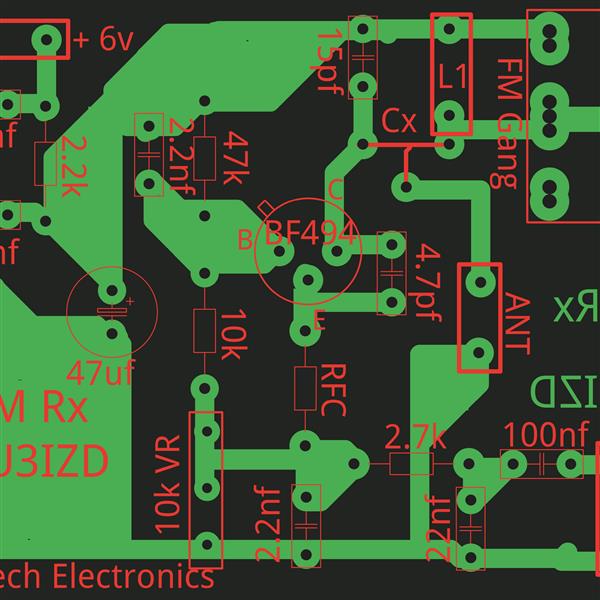
The arrangement of components on a printed circuit board is seen in figure 4.


We note that, as this is a high-frequency circuit, it is very important to keep all connections short, including the terminals of components such as the coil, and especially the variable capacitor.
The variable capacitor is of the low capacitance type used in transistor radios for the FM range with a maximum capacitance of the order of 40 or 50 pF. Larger variable capacitors, for the AM band, are not useful, because in part of the tuned band they block the oscillations, stopping the oscillator operation.
A common trimmer, from 1-15 to 5-40 pf, can also be used to obtain fixed tuning, in case of applications in remote controls, walk-talkies, etc.
The coils are made with 18 to 22 enameled AWG wire with a diameter of 1 cm without a core. The number of turns depends on the tuned band, as shown in the following table, as well as the value of capacitor C3:
C3 Turns Tuned Range (MHz)
1 1 pF 140 to 150
2 2.2 pF 120 to 140
3 3.3 pF 100 to 120
4 4.7 - 5.6 pF 75 to 100
5 to 6 5.6 - 10 pF 50 to 75
Capacitors with values smaller than 1 µF in the high frequency sector (around Q1) must be ceramic. The values of these components are important, and the reader should be careful with the markings. It is common to confuse 10k or 5k6 (lower case) which means 10 nF or 5.6 nF with 10K or 5K6 (upper case) which means 10 pF or 5.6 pF.
Resistors are all 1/8 W or larger, and other components are specs given in the bill of materials.
XRF consists of 30 or 40 turns of wire 32 or thinner on a matchstick, or drinking straw approximately 2 cm long. Commercial microshocks from 47 µH to 100 µH can also be used.
As an antenna, we can use either a piece of rigid wire 40 to 60 cm long, or a telescopic antenna of the same dimensions. We must not use an external antenna or a larger antenna, as a larger antenna "loads" the circuit, making it unstable and even preventing the oscillator stage from working.
If the reader intends to explore the entire frequency range between 50 and 150 MHz, it is interesting to place a socket for the coil and have several coils in sockets, as seen in figure 5.

Thus, by assembling the device as shown in the figure, it is possible to easily change the coils according to the range to be tuned.
TEST AND USE
To test the device, simply turn on the power and try to tune in a station by adjusting the regeneration potentiometer (P1) until you hear something.
Retouch the tuning and adjust the volume to the desired point.
It is interesting to test the operation in the FM band where it is easier to obtain a constant signal with a fixed frequency.
For ham radio, police and airplane tracks, the reader should have some patience when tuning. What happens is that the communications of these services are very short, which means that, in order to find them, you have to experiment a lot. However, once the tuning point is marked, it becomes easier to wait for communications to occur.
In the case of airplanes, unless the reader lives near major airports (São Paulo, Rio, Belo Horizonte, etc.), it will be necessary to have a little patience to find the most used frequencies in your region.
For remote control applications we have in figure 6 a relay activation circuit. The transmitter must be modulated by an audio tone.

As for adjusting the receiver in remote control applications, you can connect a multimeter (voltage scale) to the collector of Q2, or connect this point to the input of an external audio amplifier.
External Amplifier.


Schematic diagram of FM radio.👇

MATERIAL LIST
Semiconductors:
CI1 - LM386 - integrated audio amplifier
Q1 - BF494 or equivalent - high frequency NPN transistor
Q2 - BC548 or equivalent - General purpose NPN transistor
Resistors: (1/8 W x 5%)
R1 - 47k ohms
R2 - 33k ohms
R3 - 1k ohms
R4 - 3.3k ohms
R5 - 2.2k ohms
R6 - 1 M ohms
R7 - 10 ohms
P1, P2 - 10k ohms
Capacitors:
C1, C8 - 10 µF/16 V - electrolytic
C2 - 4.7 nF - ceramic
C3 - 1 pF - ceramic (see table according to frequency)
C4 - 1.2 nF - ceramic
C5 - 33 nF - ceramic or polyester
C6 - 470 nF - ceramic or polyester
C7 - 220 nF - ceramic or polyester
C9 - 47 nF - ceramic or polyester
C10 - 220 µF/12 V - electrolytic
C11 - 100 µF/12 V - electrolytic
CV - variable - see text
Several:
L1 - Coil - see text
A - telescopic antenna
S1 - Simple switch
XRF - See text - shock from 47 to 100 µH
B1 - 6 or 9 V - 4 or 6 small or medium batteries
FTE – 8 ohms x 5 cm or greater - regular speaker
Printed circuit board, battery holder, housing or mounting bracket, button for the variable capacitor, wires, solder, etc.
- Comments(0)
- Likes(3)
 More by Abel Mathews
-
 BF494 Transistor based FM radio
HOW IT WORKSAt the entrance we have a super-regenerative detector with the basic configuration shown...
BF494 Transistor based FM radio
HOW IT WORKSAt the entrance we have a super-regenerative detector with the basic configuration shown...
-
 Micro Drone With Proximity Sensing
Drones are today widely being used in a number of fields. Applicat...
Micro Drone With Proximity Sensing
Micro Drone With Proximity SensingDrones are today widely being used in a number of fields. Applicat...
-
 Raspberry pi pico based CNC plotter
Rasberry pi pico based CNC plotterAboutMy name is Abelmathews. Iam a high school student. I like to ...
Raspberry pi pico based CNC plotter
Rasberry pi pico based CNC plotterAboutMy name is Abelmathews. Iam a high school student. I like to ...


