


ACD - Accumulator Control Device for EV FSAE
Since then, we have designed and manufactured our prototypes every year with the goal of competing annually, both in Brazil and internationally. By building our vehicle, we take part in competitions organized by the Society of Automotive Engineers (SAE), which aim to promote technological development. In these competitions, participants must plan, raise funds, manage, and execute the design of a high-performance, low-cost electric vehicle, preparing themselves to meet the future demands of the automotive industry. We have had the opportunity to participate in 9 national championships and 5 international ones. After more than 10 years of history, we have achieved 7 victories in Brazilian competitions and 2 in American competitions, establishing ourselves as the Brazilian Formula SAE Electric team with the highest number of national and international titles.
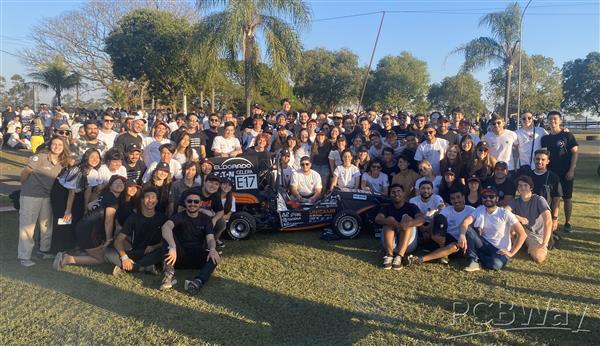
Team picture at 2023 competition
Our electronics division is responsible for the vehicle’s safety systems, data acquisition boards, dashboard, and low-voltage wiring harness. The safety system manages pre-charge, discharge, and full-load control of the inverters through a finite state machine and real-time monitoring of critical systems like the BMS (Battery Management System), IMD (Insulation Monitoring Device), and BSPD (Brake System Plausibility Device).
Beyond safety, we develop sensor boards to collect data such as cooling system temperature and suspension travel. This supports fine-tuning the vehicle's setup. We also design the dashboard electronics, which provide visual feedback to the driver, helping adapt the car's response to driving conditions.
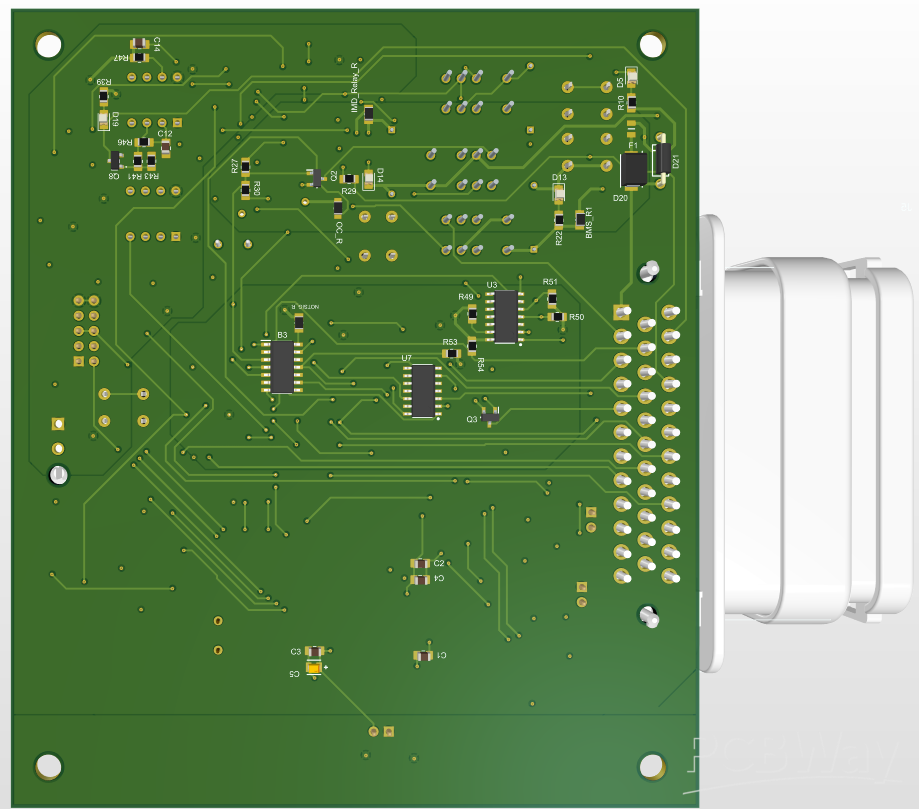
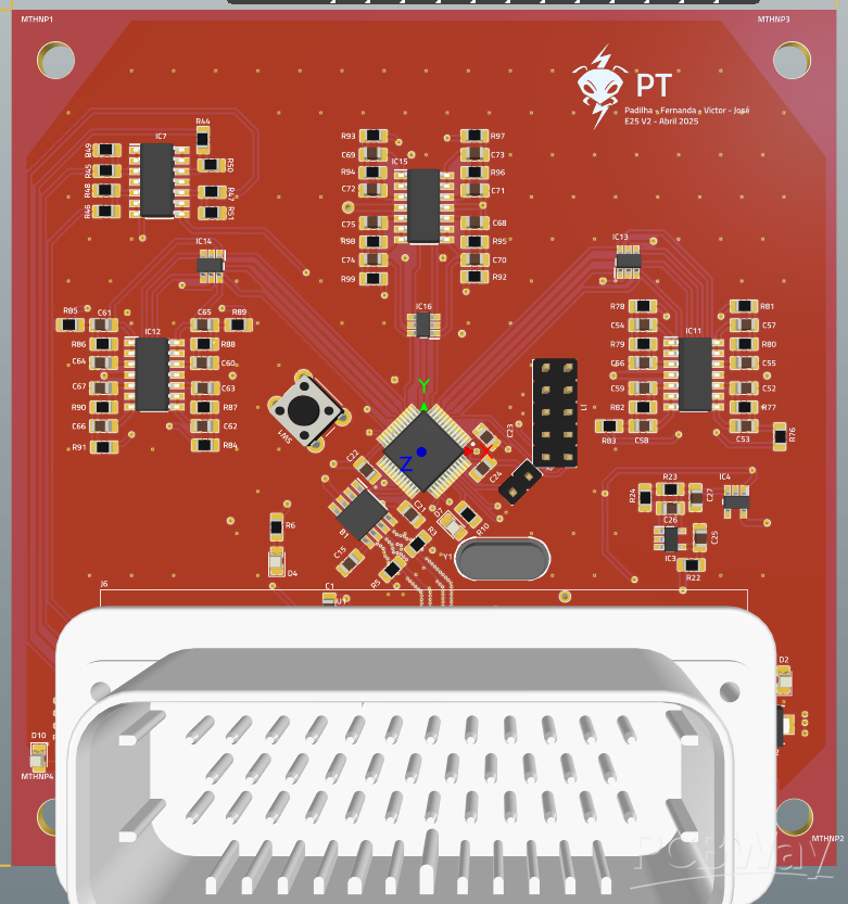
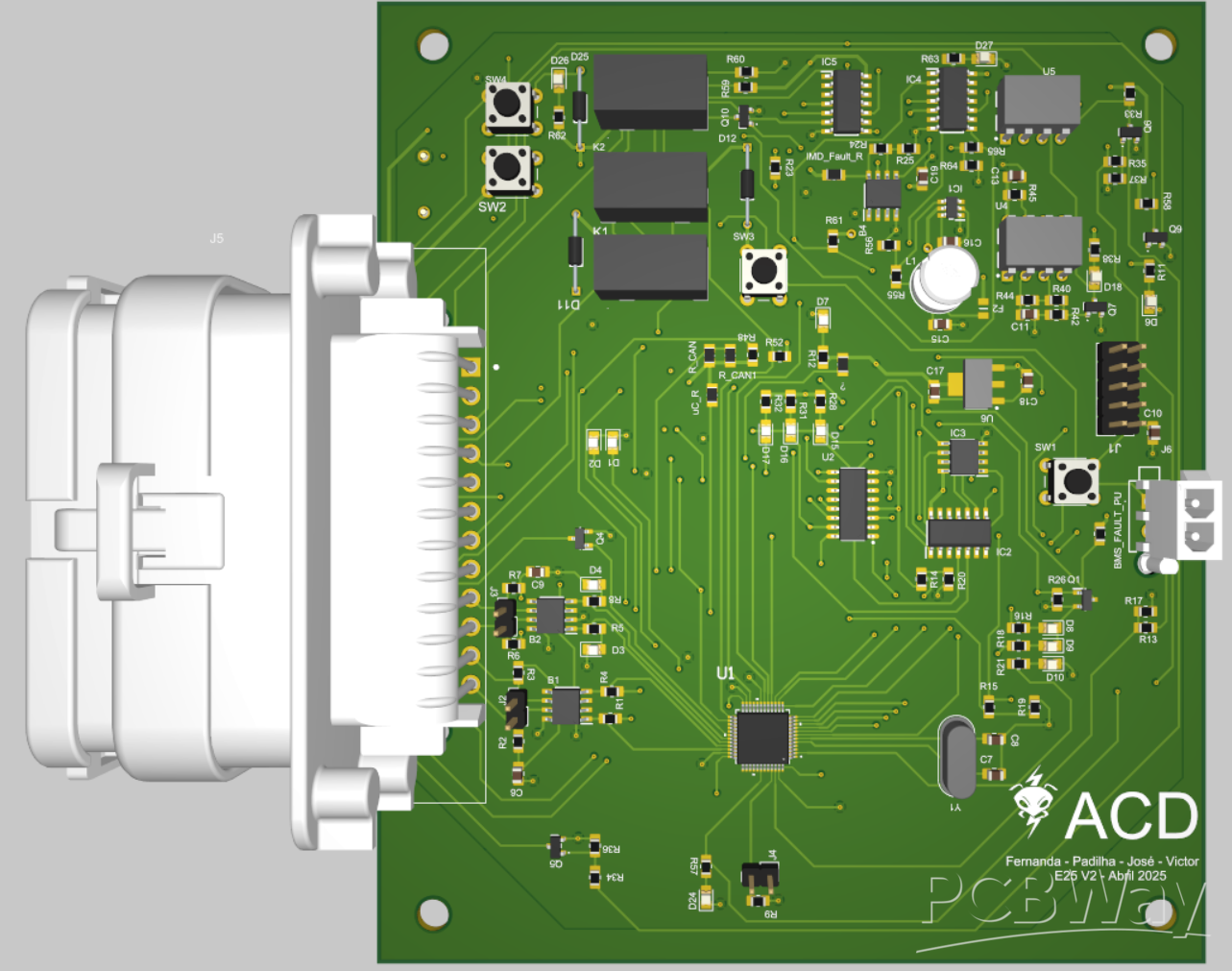
One of the PCBs developed by Unicamp E-Racing’s electronics division is the Accumulator Controller Device (ACD), responsible for managing charge and discharge values in the car’s high-voltage system. The ACD's main functions include controlling the pre-charge and discharge logic of the inverter, monitoring and executing fault logic from the Battery Management System (BMS), Insulation Monitoring Device (IMD), and Autonomous System (AS), and sending shutdown signals in case of faults. The design of the ACD was based on an older board called ASMD, which included many of the same features, with some additions and omissions. Most functionalities of the ACD are implemented through a state machine architecture programmed into an STM32G4 microcontroller, with a scheduling system to handle priorities and timing. While the pre-charge and discharge circuits are primarily hardware-based using logic gates and relays, the timing control is handled by the microcontroller. Additionally, the ACD includes CAN communication, enabling efficient data exchange with other PCBs in the car, ensuring full system integration.
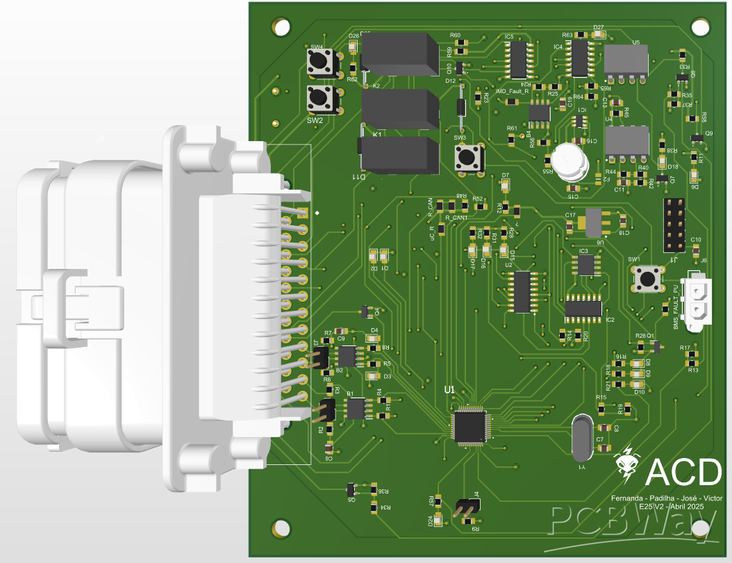
The current version of the ACD is version 2, developed as an improvement over the initial prototype. Testing of the first version focused on validating each part of the project individually. These tests were conducted both on the bench using development boards and breadboards, as well as directly on the PCB. Component soldering was performed in stages, with each section being assembled according to the testing demands. The microcontroller and power supply ICs were soldered first to ensure the board's basic functionality. Despite these early difficulties, most sections of the first version were successfully validated. The changes and improvements made based on these results were implemented in the current v2 design.
Several improvements were made in version 2 (v2) of the ACD based on the experience with the first version:
- IMD Signal Handling
A new component was added to better interpret the IMD fault signal, which operates with different voltage levels depending on the fault condition. The circuit now ensures the board can correctly recognize these conditions while remaining safe for the microcontroller.
- Logic Inverter Added:
A logic inverter was included to make sure the fault indicator LEDs work properly. This is because the fault signals operate at low Voltage, while the LED drivers need a high signal to turn on.
- Signal Adjustment for Retry Function
Some signal voltages were changed from 12V to 5V, requiring resistor updates. A manual retry button was also added for a specific safety function, located in the cockpit.
- Debug LEDs:
Five LEDs were added—two to confirm the power supply voltages are present and three for general use, such as showing which state the system is in.
- Connector Updates:
The connectors used to link the ACD to other systems like ASD, BSPD, and the wiring harness were updated to improve compatibility and reliability.
- Four-Layer PCB
The board now uses a four-layer structure (Signal – Ground – Power – Signal), which helps reduce electrical noise and improve data reliability by better isolating signals.
PCBWay's support plays a key role in helping us develop more reliable and efficient systems. With their help, we can push our project further, improve performance, and gain valuable experience in PCB design and manufacturing. We're excited about the opportunity to work alongside PCBWay and bring our goals to life through this partnership.
Apply for sponsorship >>- Comments(0)
- Likes(1)
 More by Engineer
-
 PDP - Placa do Pack - Accumulator Sensing Board
Since then, we have designed and manufactured our prototypes every year with the goal of competing a...
PDP - Placa do Pack - Accumulator Sensing Board
Since then, we have designed and manufactured our prototypes every year with the goal of competing a...
-
 Placa Traseira (Rear Board) – Data Acquisition FSAE EV
Founded in 2011, our team took on the challenge of building one of Brazil's first Formula SAE electr...
Placa Traseira (Rear Board) – Data Acquisition FSAE EV
Founded in 2011, our team took on the challenge of building one of Brazil's first Formula SAE electr...
-
 ACD - Accumulator Control Device for EV FSAE
Since then, we have designed and manufactured our prototypes every year with the goal of competing a...
ACD - Accumulator Control Device for EV FSAE
Since then, we have designed and manufactured our prototypes every year with the goal of competing a...


